Air treatment device for agricultural buildings

a technology for air treatment devices and agricultural buildings, applied in lighting and heating equipment, human health protection, separation processes, etc., can solve problems such as unpleasant gases, potential dangers, and agricultural businesses that are often subject to difficult market conditions, and achieve the effect of increasing the moisture content of air treatment materials

Inactive Publication Date: 2007-03-01
JOHNSON MATTHEW W +1
View PDF2 Cites 3 Cited by
  • Summary
  • Abstract
  • Description
  • Claims
  • Application Information

AI Technical Summary

Benefits of technology

[0006] One embodiment of the invention is an apparatus for treating air from an exhaust port of a building. The apparatus includes an enclosed pathway for connection to the exhaust port of the building and a non-linear pathway extending from the inlet to a discharge outlet. The apparatus further includes air treatment material positioned along at least a portion of the pathway so that air is exposed to the air treatment material as it moves through the pathway. Yet another embodiment of the invention includes an irrigation system for increasing the moisture content of the air treatment material. The irriga

Problems solved by technology

Not only are these gases unpleasant and potentially dangerous for those who are located near waste collection areas, but many regulatory bodies regulate the permitted emissions of certain gases from an agricultural operation.
Compounding the problem is that agricultural businesses are often subjected to difficult market conditions, requiring that the livestock producer hold down costs.
However, forcing air through a thick field of biofilter material creates head loss on the exhaust fan, resulting in a need for more a powerfu

Method used


Image

  • Air treatment device for agricultural buildings
  • Air treatment device for agricultural buildings
  • Air treatment device for agricultural buildings

Examples


Embodiment Construction

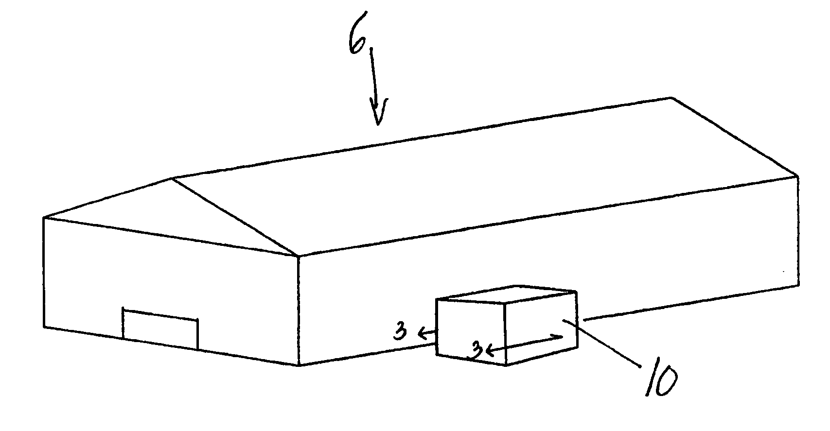
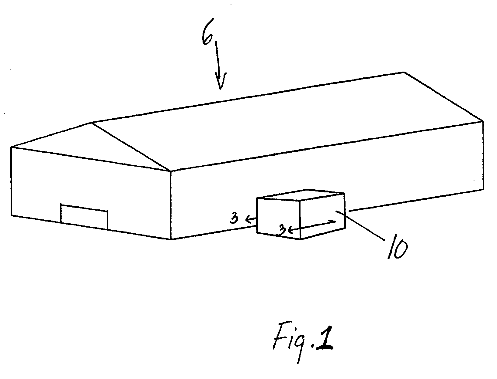
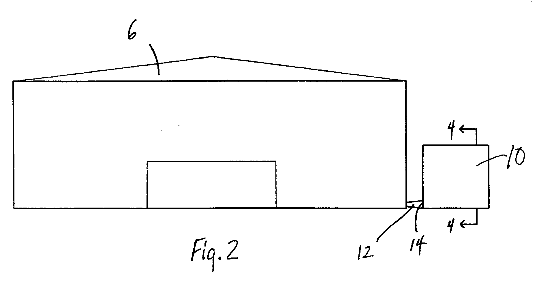
[0014]FIGS. 1 and 2 illustrate an agricultural building 6 that is coupled to an exhaust treatment member 10 in accordance with one embodiment of the invention. The agricultural building 6 is coupled to the exhaust treatment member 10 on the output side of an exhaust fan (not shown) that is positioned to draw air out of the agricultural building. The exhaust fan is positioned near a manure pit (not shown) to evacuate air in the manure pit area, although the exhaust fan may be located anywhere as long as it can draw air out of the agricultural building 6. The agricultural building 6 is coupled to a treatment member inlet 14 on the exhaust treatment member 10 through a duct 12. Duct 12 has an interior cross section that is approximately the same or larger than an output port (not shown) on the output side of the exhaust fan at the location where output port is coupled to the duct 12. The interior cross sectional area of duct 12 is generally constant or increasing from the output port t...


PUM


Abstract

An apparatus for treating air from an exhaust port of a building. The apparatus includes an enclosed pathway having an inlet for communication with an exhaust port, a discharge outlet, and a non-linear pathway portion between the inlet and discharge outlet. The non-linear pathway includes air treatment material positioned in communication with a portion of the pathway to expose the air to the air treatment material as it moves through the pathway. The apparatus includes an irrigation system for maintaining the moisture content of the air treatment material.

Description

FIELD OF THE INVENTION [0001] The present invention relates generally to the field of odor control in agricultural applications. More particularly, the invention relates to structures for reducing or controlling emissions of odorous gases from agricultural buildings or other similar structures. BACKGROUND OF THE INVENTION [0002] Unwanted by-products of producing livestock include the inherent odors, particularly those created by livestock waste. Livestock waste emits foul and noxious gases, including hydrogen sulfide and ammonia. Not only are these gases unpleasant and potentially dangerous for those who are located near waste collection areas, but many regulatory bodies regulate the permitted emissions of certain gases from an agricultural operation. Further, some regulatory bodies require larger agricultural operations to provide air emission plans, which include methods and practices that will be employed by the agricultural operations to minimize emissions of certain gases and p...

Claims


Application Information

Patent Timeline
IPC IPC(8): F26B21/06
CPCA61L9/013B01D53/77Y02A50/2359B01D2258/05B01D53/85Y02A50/20
Inventor JOHNSON, MATTHEW W.JOHNSON, DENNIS J.
Owner JOHNSON MATTHEW W
Why Eureka
Try Eureka