Preparation of asymmetric polyethylene hollow fiber membrane
a polyethylene and hollow fiber technology, applied in the field of preparing asymmetric polyethylene hollow fiber membranes, can solve the problems of unsatisfactory water permeability and particle cut-off properties of uniform pore-sized hollow fiber membranes, small final pores, and large pore sizes
- Summary
- Abstract
- Description
- Claims
- Application Information
AI Technical Summary
Benefits of technology
Problems solved by technology
Method used
Image
Examples
example 1
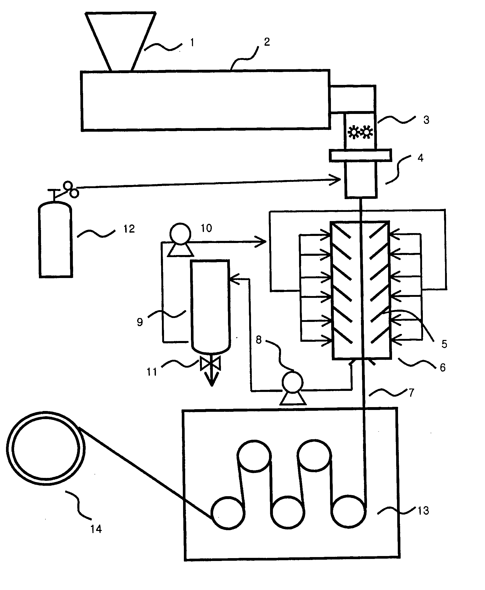
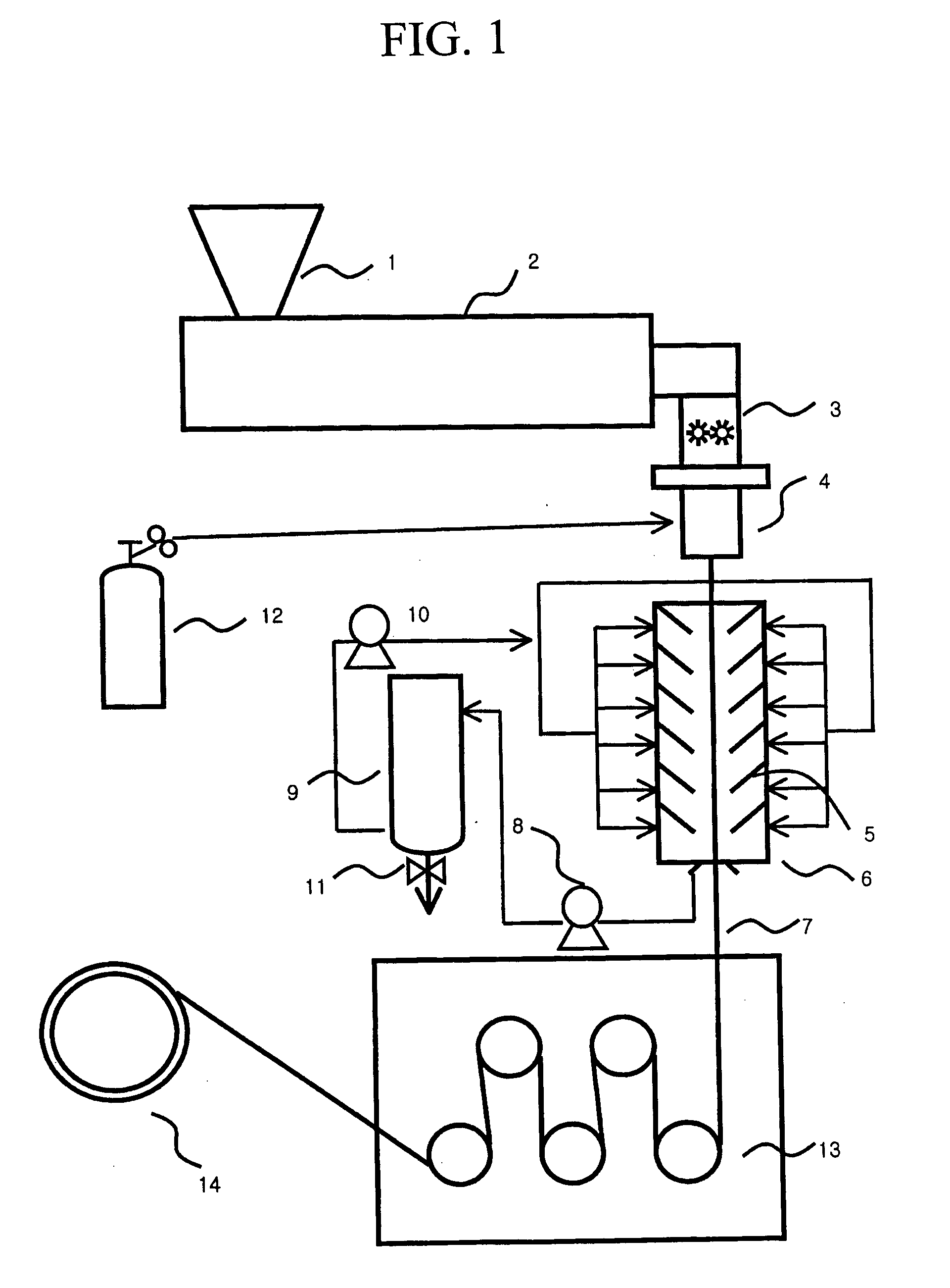
[0041] A polyethylene resin having a melt index of 0.35 g / 10 min and a density of 0.963 g / cm3 was melt-spun at 180° C. through a spinneret having a double nozzle slit form while injecting a nitrogen gas flow into the inner nozzle of the spinneret. The spun hollow fiber was solidified by passing successively through a cooling zone disposed just below the nozzle where liquid freon kept at 20° C. was sprayed downward (co-currently) at a rate of 2 m / sec through multiple spray nozzles so that the freon spray contacts and cools the outer surface of the spun hollow fiber. The solidified hollow fiber was wound on a winding bobbin via rollers and annealed at 120° C. for 24 hrs. The annealed hollow fiber was cold-stretched (room temperature) to the extent of 50% at a deformation rate of 110% per second. Then, the cold-stretched hollow fiber was hot-stretched to the extent of 600% at 110° C., at a deformation rate of 5% per second, to form a stretched hollow fiber, which was heat-set at 115° C...
examples 2 and 3
, AND COMPARATIVE EXAMPLES 1 TO 5
[0043] The procedures of Example 1 were repeated except for changing the cooling medium and conditions as specified in Table 1, to obtain various hollow fiber membranes. The properties of the hollow fiber membranes thus obtained were determined and the results are showed in Table 1.
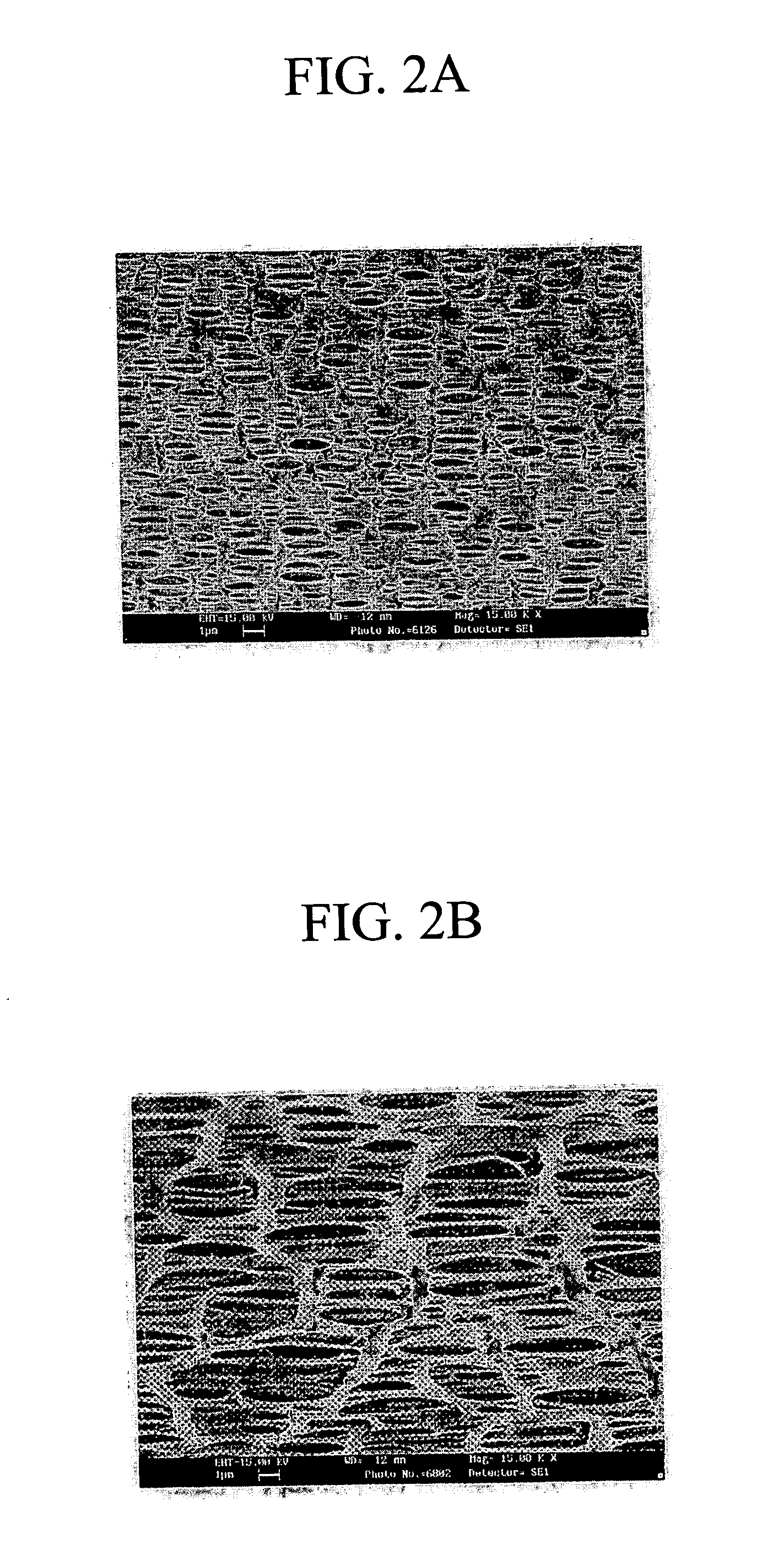
[0044] Further, SEM photographs of the outer and inner wall surfaces of each of the hollow fiber membranes obtained in Example 1 and Comparative Examples 1 to 5 are shown in FIGS. 2A and 2B, 3A and 3B, 4A and 4B, 5A and 5B, 6A and 6B, and 7A and 7B, respectively. FIGS. 2A and 2B (Example 1) show that its outside has much more small pores, i.e., more porous, than the inside. In contrast, FIGS. 3 and 4 (Comparative Examples 1 and 2, respectively) show that the outside (A) and inside (B) pore structures are similar to each other, and FIGS. 5 and 6 (Comparative Examples 3 and 4, respectively) show that the outside has small pores, but only a few in number, i.e., less porous, ...
PUM
| Property | Measurement | Unit |
|---|---|---|
| Temperature | aaaaa | aaaaa |
| Temperature | aaaaa | aaaaa |
| Temperature | aaaaa | aaaaa |
Abstract
Description
Claims
Application Information
 - R&D
- Intellectual Property
- Life Sciences
- Materials
- Tech Scout
- Unparalleled Data Quality
- Higher Quality Content
- 60% Fewer Hallucinations
Browse by: Latest US Patents, China's latest patents, Technical Efficacy Thesaurus, Application Domain, Technology Topic, Popular Technical Reports.
© 2025 PatSnap. All rights reserved.Legal|Privacy policy|Modern Slavery Act Transparency Statement|Sitemap|About US| Contact US: help@patsnap.com


