Carbon dioxide nanosensor, and respiratory CO2 monitors

a carbon dioxide and nanosensor technology, applied in the field of nanostructured sensor systems, can solve the problems of limited use of these sensors, limited use of current cosub>2 /sub>sensors restricting the use of capnography, bulky and expensive non-dispersive, etc., to achieve the effect of reducing the cost of the sensor component, and low power consumption

Inactive Publication Date: 2007-03-01
NANOMIX
View PDF51 Cites 138 Cited by
  • Summary
  • Abstract
  • Description
  • Claims
  • Application Information

AI Technical Summary

Benefits of technology

[0020] Particular examples of medical systems having aspects of the invention are described, employing nanosensors for measuring CO2 so as to overcome limitations of the prior art. Such novel nanoelectronic systems offer: (i) performance that matches or exceeds that of infrared technology, (ii) plug-and-play simplicity in a disposable package, (iii) the small size and low power consumption needed for wireless integration and (iv) the ability to incorporate arrays of sensors on a single chip or substrate. This CO2 sensing technology offers an order of magnitude reduction in the cost of the sensor component.

Problems solved by technology

Size, cost, and power constraints result in only limited use of these sensors.
The high cost and limitations of current CO2 sensors restrict the use of capnography to high value, controlled environments, such as surgical wards.
To meet the necessary specifications of such capnography device, current technology relies on bulky and expensive non-dispersive infrared absorption (NDIR) sensors to determine CO2 concentration.
The high cost and limitations of this technology restrict the use of capnography to high value, controlled environments, such as surgical wards.

Method used


Image

  • Carbon dioxide nanosensor, and respiratory CO2 monitors
  • Carbon dioxide nanosensor, and respiratory CO2 monitors
  • Carbon dioxide nanosensor, and respiratory CO2 monitors

Examples


Embodiment Construction

Nanosensor Architecture

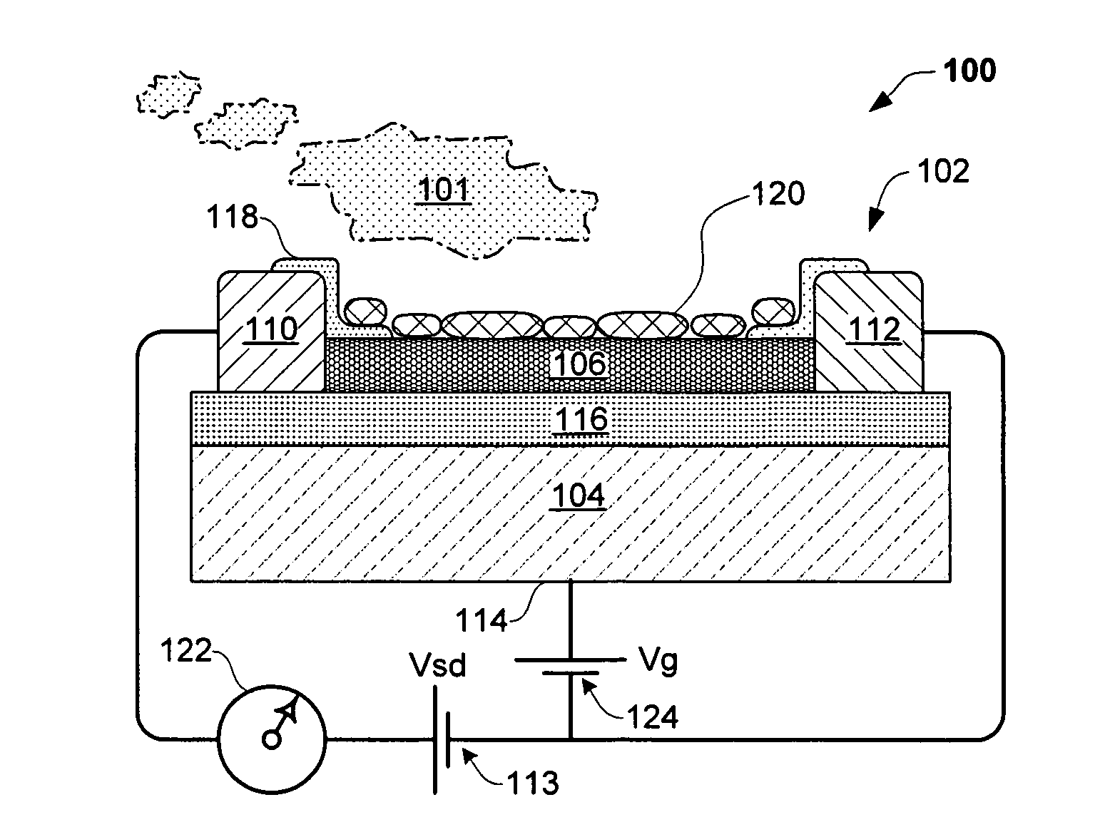
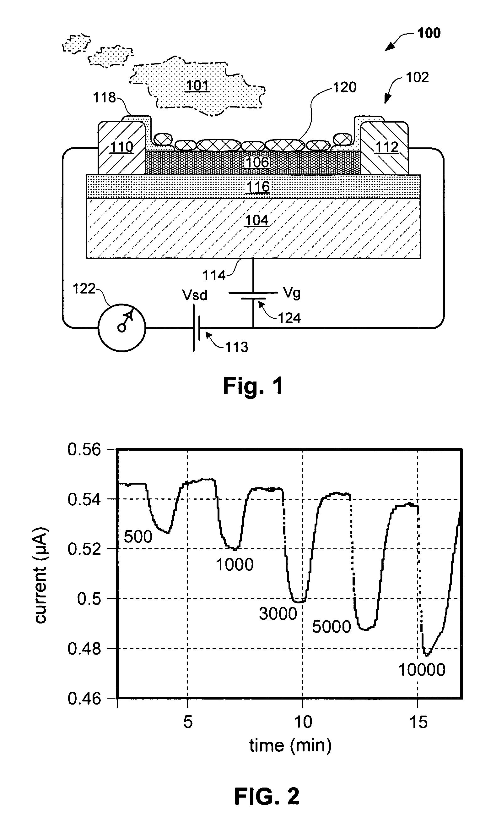
[0065]FIG. 1. shows an exemplary electronic sensing device 100 having aspects of the invention, for detecting an analyte 101 (e.g. CO2, H2 or NO, and the like), comprising a nanostructure sensor 102. Sensor 102 comprises a substrate 104, and a conducting (e.g., semiconducting) channel or layer 106 comprising a nanostructure material, such as a nanotube or network of nanotubes, disposed on the substrate. The nanostructure material 106 may contact the substrate as shown, or in the alternative, may be spaced a distance away from the substrate, with or without a layer of intervening material.

[0066] In an embodiment of the invention, conducting channel 106 may comprise one or more carbon nanotubes. For example, conducting channel 106 may comprise a plurality of nanotubes forming a mesh, film or network. Certain exemplary embodiments having aspects of the invention include nanostructure elements which may be made using chemical vapor deposition (CVD) and tradition...


PUM

PropertyMeasurementUnit
thickaaaaaaaaaa
thickaaaaaaaaaa
thickaaaaaaaaaa

Abstract

An electronic system and method for detecting analytes, such as carbon dioxide, is provided, using an improved nanostructure sensor (CO2 sensor). The CO2 sensor may comprise a substrate and a nanostructure, such as a one or more carbon nanotubes disposed over the substrate (e.g., as a network). One or more conductive elements may electrically communicate with the nanostructure. A counter or gate electrode may be positioned adjacent the nanostructure. A functionalization material reactive with carbon dioxide may be included, either disposed in contact with the nanostructure or isolated by a dielectric. The sensor may be connected to a circuit responsive to changes in CO2 concentration in the environment. Embodiments are described of medical sensing systems including one or more CO2 sensors. One embodiment comprises a breath sampling cannula which is connected to a sensor unit. In an alternative, the cannula permits supplemental oxygen to be administered, while recovering and measuring analytes in breath samples. The cannula may connect to a portable processor-display unit for monitoring one or more analytes, such as CO2. Another embodiment includes a cannula configured for the monitoring of sleep disorders, such as apnea, comprising one or more sensors disposed adjacent a breath sampling channel, optionally including flow rate or other sensors. The sensors may be connected by wired or wireless links for to a processor/input/display unit. Any of the embodiments may include filters, selectively permeable membranes, absorbents, and the like to precondition the breath sample, may be configured to include complementary chemistry measurements.

Description

CROSS-REFERENCE TO RELATED APPLICATIONS [0001] This application is a continuation-in-part of and claims priority to U.S. patent application Ser. No. 10 / 656,898 filed Sep. 5, 2003 entitled “Polymer Recognition Layers For Nanostructure Sensor Devices” (published US 2005-0279,987), which in turn claims priority to Provisional Application No. 60 / 408,547 filed Sep. 5, 2002. [0002] This application is a continuation-in-part of and claims priority to U.S. patent application Ser. No. 10 / 940,324 filed Sep. 13, 2004 entitled “Carbon Dioxide Nanoelectronic Sensor” (published US 2005-0129,573), which in turn claims priority to U.S. Provisional Patent Application No. 60 / 502,485 filed Sep. 12, 2003. [0003] This application is a continuation-in-part of and claims priority to U.S. patent application Ser. No. 11 / 019,792 filed Dec. 18, 2004 entitled “Nanoelectronic capnometer adapter” (published US 2005-0245,836); which in turn claims priority to U.S. Provisional Patent Application No. 60 / 531,079, fi...

Claims


Application Information

Patent Timeline
Patent Type & Authority Applications(United States)
IPC IPC(8): G01N31/22
CPCB82Y15/00B82Y30/00G01N33/497G01N33/004G01N27/4146
Inventor CHANG, DANIEL M.CHANG, YING-LANGABRIEL, JEAN-CHRISTOPHE P.JOSHI, VIKRAMMICKELSON, WILLIAMNIEMANN, JOSEPHPASSMORE, JOHN LORENSTAR, ALEXANDERVALCKE, CHRISTIAN
Owner NANOMIX
Why Eureka
Try Eureka