
Thermoplastic nanocomposite resin composite materials

a composite material and thermoplastic technology, applied in the field of nanoparticles, can solve the problems of poor thermal resistance, abrasion resistance and rigidity of thermoplastic resins, resin composite materials prepared by blending inorganic fillers and thermoplastic resins, and lack of sufficient reinforcing effect, etc., to achieve the effect of improving physical and mechanical properties

Inactive Publication Date: 2007-03-01
CHEIL IND INC
View PDF25 Cites 20 Cited by
  • Summary
  • Abstract
  • Description
  • Claims
  • Application Information

AI Technical Summary

Benefits of technology

[0012] In some embodiments the composite material additionally comprises a thermoplastic resin. In some embodiments, the rubber-modified graft copolymer and the metal (oxide) nanoparticles are dispersed in a matrix of the thermoplastic resin. Such a dispersion may provide enhanced physical and mechanical properties to the thermoplastic resin as further described herein. In some embodiments, the thermoplastic resin comprises one or more selected from acrylonitrile-butadiene-styrene copolymer (ABS); acrylonitrile-acrylic rubber styrene copolymer resin (AAS), acrylonitrile-ethylenepropylene rubber-styrene copolymer resin, and acrylonitrile-styrene copolymer (SAN) resin. In one particular embodiment, the thermoplastic resin is a SAN resin.

Problems solved by technology

However, thermoplastic resins may have poor thermal resistance, abrasion resistance and rigidity.
However, resin composite materials prepared by blending inorganic filler and a thermoplastic resin lack a sufficient reinforcing effect because the bonding strength between the inorganic filler and the matrix resin is weak.
Further, large amounts of inorganic filler may cause serious deterioration of impact strength.
The preparation of nanoscale materials with unique properties represents a significant challenge.

Method used


Image

  • Thermoplastic nanocomposite resin composite materials

Examples


examples

[0063] Each component of (A) rubber-modified graft copolymer, (B) colloidal metal (oxide) nanoparticles, (C) rubber-modified graft copolymer / metal (oxide) nanoparticle composite, (D) copolymer of vinyl cyanide compound and aromatic vinyl compound, (E) fumed silica and (F) silicone impact modifier used in Examples and Comparative Examples was prepared as follows:

(A) Rubber-Modified Graft Copolymer (g-ABS resin)

[0064] A rubber-modified graft copolymer was prepared using 50 parts by weight of polybutadiene, 15 parts by weight of acrylonitrile and 35 parts by weight of styrene.

(B) Colloidal Metal (oxide) Nanoparticles

[0065] (b1) Colloidal silica sol having an average particle size of 20 nm and containing less than 0.35% by weight of Na2O at pH 8-11 was used.

[0066] (b2) Colloidal silica sol having an average particle size of 40-60 nm and containing less than 0.35% by weight of Na2O at pH 8-11 was used.

[0067] (b3) Colloidal silica sol having an average particle size of 70-100 nm a...

examples 1-6

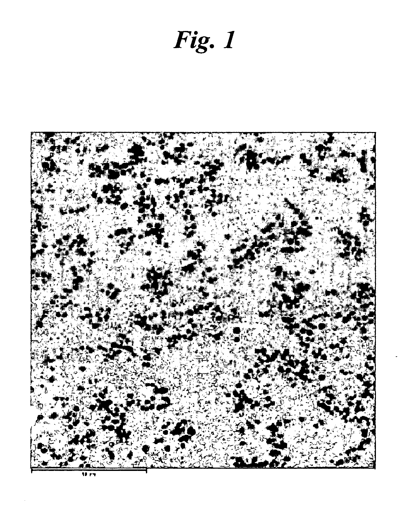
[0077] The components as shown in Table 1 were mixed and the mixture was melted and extruded through a twin screw extruder with L / D=29 and Φ=45 mm in pellets. The cylinder temperature of the extruder was kept at 220° C. The pellets were dried at 80° C. for 6 hours. The dried pellets were molded into test specimens using a 6 oz injection molding machine at molding temperature of 240-280° C., and barrel temperature of 60-80° C. The transmission electron micrograph (TEM) of a thermoplastic nanocomposite resin obtained in Example 1 is shown in FIG. 1. As shown in FIG. 1, the nanoparticles are uniformly dispersed throughout the matrix.


PUM

PropertyMeasurementUnit
Percent by massaaaaaaaaaa
Forceaaaaaaaaaa

Abstract

A polymer composite material includes metal (oxide) nanoparticles adsorbed on the surface of a rubber-modified graft copolymer. Some embodiments may additionally comprise a thermoplastic resin in which the nanoparticles and rubber-modified graft copolymer are dispersed. In some embodiments, the composite materials have improved impact strength, tensile strength, heat resistance, and flexural modulus.

Description

CROSS-REFERENCE TO RELATED APPLICATIONS [0001] This application is a continuation-in-part application under 35 U.S.C. § 365(c) claiming the benefit of the filing date of PCT Application No. PCT / KR2005 / 004496 designating the United States, filed Dec. 23, 2005. The PCT Application claims the benefit of the earlier filing date of Korean Patent Application No. 10-2005-0077955, filed Aug. 24, 2005. The contents of the PCT Application and Korean Patent Application No. 10-2005-0077955 are incorporated herein by reference in their entirety.BACKGROUND OF THE INVENTION [0002] 1. Field of the Invention [0003] The present invention relates to nanoparticles in combination with polymers. [0004] 2. Description of the Related Art [0005] Thermoplastic resins are widely used because of their light weight and excellent moldability. However, thermoplastic resins may have poor thermal resistance, abrasion resistance and rigidity. In recent years, there has been a continuing effort to develop thermoplast...

Claims


Application Information

Patent Timeline
IPC IPC(8): C08K3/22
CPCB82Y30/00C08F6/18C08F279/02C08F279/04C08F285/00C08L51/04C08L55/02C08L2666/02B82B3/00B82Y40/00C08F253/00
Inventor KIM, IL JINJOO, HOJEONG, DONG WOOKKANG, SOON KUN
Owner CHEIL IND INC
Learn More