
Method for testing and controlling workflows in a clinical system and/or components thereof

a clinical system and workflow technology, applied in the direction of instruments, multi-programming arrangements, ultrasonic/sonic/infrasonic diagnostics, etc., can solve the problems of relatively time-consuming and costly tests, complex interaction of all variants, and inability to exact conclusion of how such a medical-technical system behaves in the clinical environment. achieve the effect of simple and cost-effectiv

Inactive Publication Date: 2007-03-01
SIEMENS HEALTHCARE GMBH
View PDF21 Cites 16 Cited by
  • Summary
  • Abstract
  • Description
  • Claims
  • Application Information

AI Technical Summary

Benefits of technology

[0007] An object of the present invention is to provide a simple and cost-effective method to test a clinical and / or medical-technical system that supplies reliable conclusions about the clinical and / or medical-technical system, particularly about its performance.
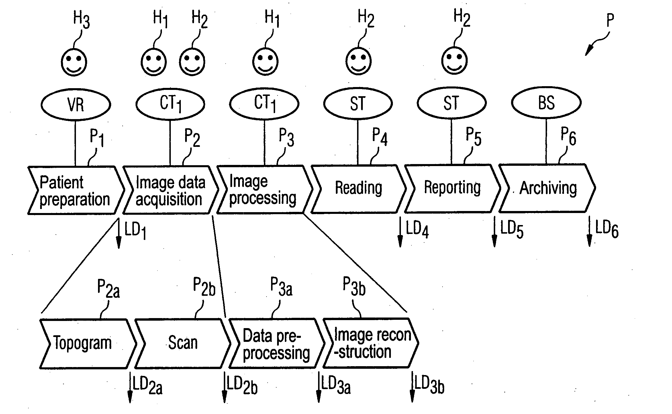
[0014] The performance data in for each process unit can be determined by means of the transfer function. The performance data themselves can also be viewed as a type of output parameters and be correspondingly further processed. In the inventive test method, precise performance data can be acquired relatively simply and quickly, even from very complex medical-technical systems. In particular the expected clinical environment of a medical-technical system can be taken into account by the examination workflows in the associated clinical system being simulated within the test with the medical-technical system being a component of the clinical system. The method can run almost completely automatically, such that—in contrast to typical test methods—the time cost for the persons or evaluators associated with the test is relatively low. Moreover, not only performance data about the individual process units or system components within the clinical environment, but also performance data of the complete clinical system (which includes a number of medical-technical systems as system components) can be acquired with the inventive test method.
[0020] In a clinical system it necessarily occurs that such a system component is already blocked by another process, for example is used for other examinations, or that the system component is faulty. It is likewise also possible that suitable system components are no longer currently available from a group of system components. In this case, the examination workflow cannot be continued. In a simulation, an examination workflow to be simulated is therefore advantageously blocked by the appertaining process unit as long as the determined system component is not available, or no system component from the group of system components is available for associated with the appertaining process unit. The corresponding wait time during which the process unit is blocked is then advantageously protocolled and / or output as a type of performance data of this process unit, such that downtimes that arise due to such blockages can also be revealed and possibly reduced.
[0027] This approach has the advantage that, in existing “test tools” with which examination workflows can be simulated in the inventive manner, individual process units can very easily be replaced at a later point in time with “sub-processing units” which describe the real process in more detail. This means that, for example, a first version of a suitable test tool can initially be created with which the inventive method can be implemented in a relatively rough manner. As soon as new data for individual system components are then available, suitable sub-process units can then be created on the basis of these data, which sub-process units more exactly represent the sub-processes of the examination workflow reproduced by existing process units.
[0034] In the inventive method for controlling medical examination workflows in a clinical and / or medical-technical system with a number of system components networked among one another, control parameters for the clinical and / or medical-technical system and / or its system components can then be determined using the determined system optimization target data and / or system component optimization target data. These control parameters can be automatically transferred to the clinical and / or medical-technical system or, respectively, the appertaining system components. A typical example for this is that within such a simulation it is detected that, within a network of a clinical system, the computer capacity for specific process units is not sufficient and is thereby leading to unnecessary delays or blockades, and that on the other hand specific system components that are associated with other process units are not being operated at full capacity. By suitable adjustment of control parameters of the appertaining system components and / or of the network, the free computer capacities can then be provided for the process units that run unnecessarily slow. The performance of the total system can be increased automatically and without additional costs in this manner.

Problems solved by technology

The interaction of all variants is very complex.
An exact conclusion of how such a medical-technical system behaves in the clinical environment is generally not possible.
Moreover, such tests are relatively time-consuming and costly due to the number of persons involved therewith.

Method used


Image

  • Method for testing and controlling workflows in a clinical system and/or components thereof
  • Method for testing and controlling workflows in a clinical system and/or components thereof
  • Method for testing and controlling workflows in a clinical system and/or components thereof

Examples


Embodiment Construction

[0048] Both clinical and / or medical-technical systems are capable of being tested with the aid of the inventive test method, by examination workflows being simulated within the appertaining systems.

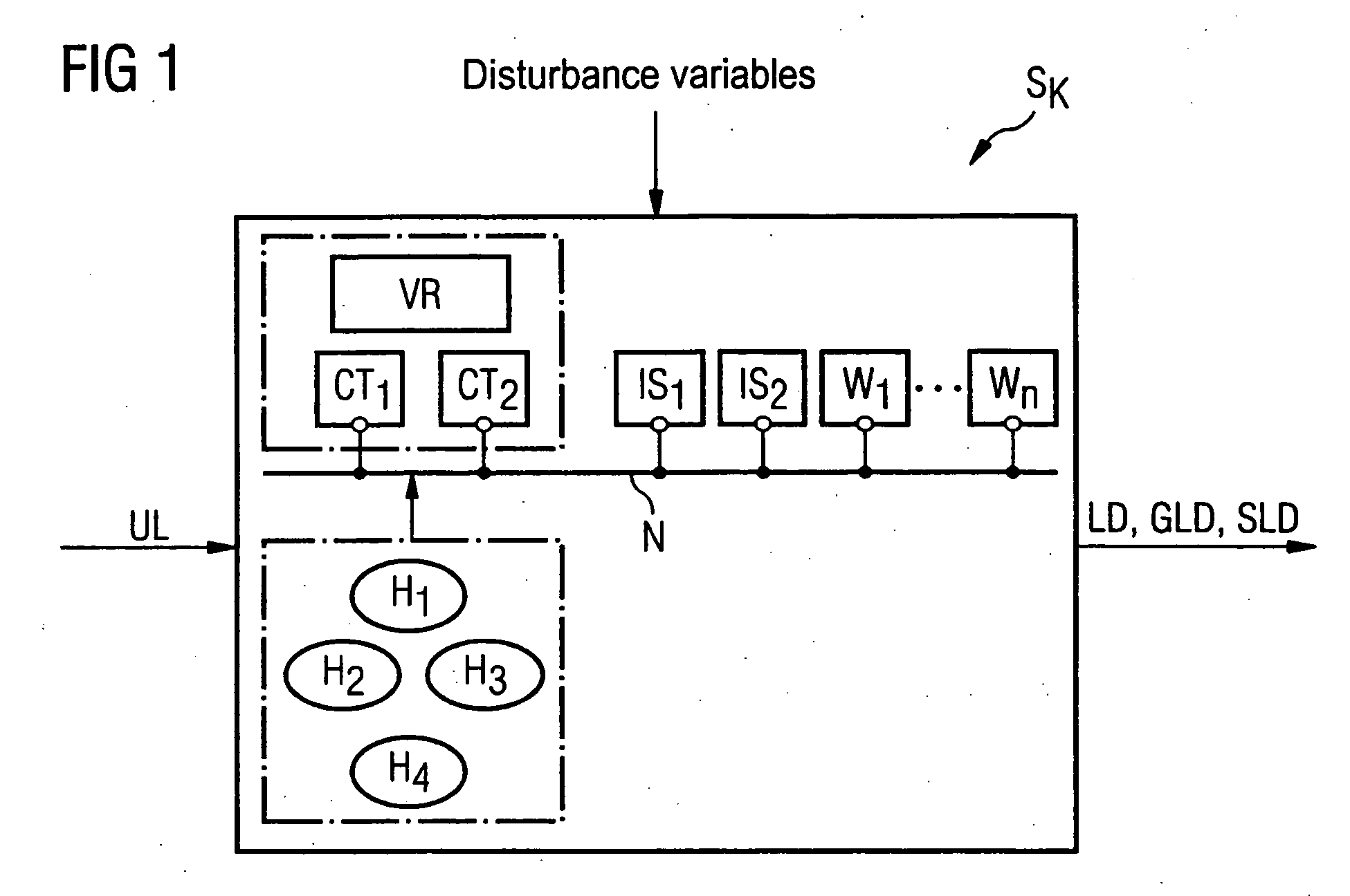
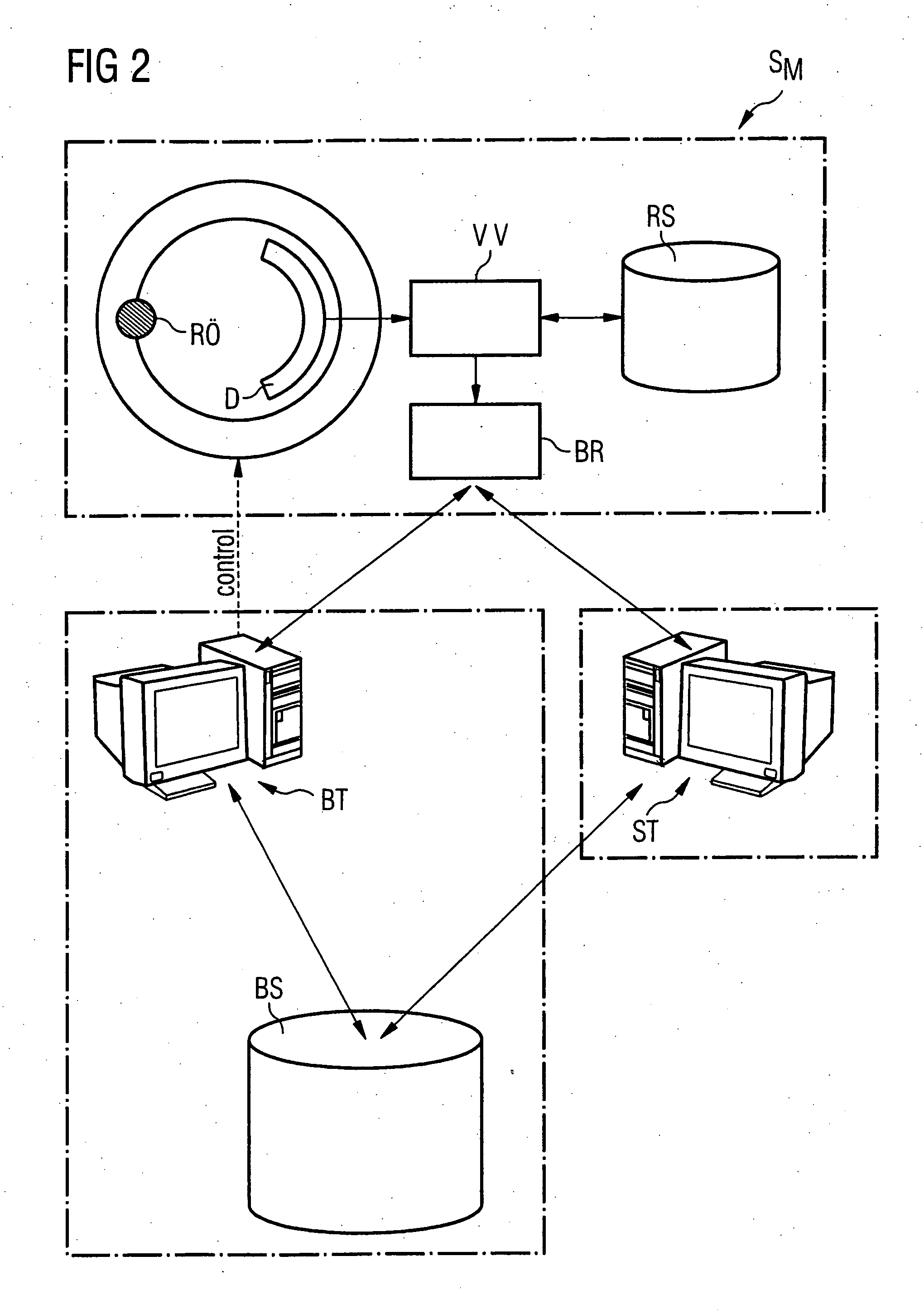
[0049]FIG. 1 gives an overview of a clinical system SK. As can be seen in FIG. 1, a clinical system SK has one or more modalities CT1, CT2. The shown example is a clinical system SK with two modalities CT1, CT2, namely two computed tomography apparatuses CT1, CT2. As medical-technical systems, these computed tomography apparatus CT1, CT2 can likewise be considered in greater detail and inventively tested by simulations. This can subsequently described using FIG. 2.

[0050] In the test of a clinical system SK, however, the focus also includes the analysis of the other participating system components, i.e. not only on the medical-technical systems, which here are initially considered as “black box” system components. In addition to the modalities CT1, CT2, the clinical system SK normally fu...


PUM


Abstract

In a method to test a clinical and / or medical-technical system and a method for controlling medical-technical examination workflows in a clinical and / or medical-technical system, medical examination workflows in the appertaining system are simulated. For this purpose, a process workflow plan is selected from a number of process workflow plans dependent on an examination task, each of the process workflow plans including a number of linked process units with which system component of the system are respectively associated. Each process workflow plan also includes an input parameter set, an output parameter set and a transfer function that is dependent on the examination task and / or the associated system component. Respective output parameter values and / or performance data for the individual process units are then determined from a number of input parameter values for the appertaining process units on the basis of the transfer function. Respective output parameter values of a process unit are used as input parameter values for a subsequent process unit within the process workflow plan.

Description

BACKGROUND OF THE INVENTION [0001] 1. Field of the Invention [0002] The invention concerns a method to test a clinical and / or medical-technical system with a number of system components as well as a method for controlling medical-technical examination workflows in such a system. [0003] 2. Description of the Prior Art [0004] Large medical apparatuses (also called “modalities”) such as computed tomography systems, magnetic resonance tomography systems, x-ray systems, ultrasound systems, angiography systems and similar apparatuses are extraordinarily complex medical-technical systems. Such systems include a number of quite different system components. In particular, different hardware components such as data acquisition devices, cooling devices, control computers etc. are present in such systems as well as software components such as different types of image evaluation software or applications with special monitoring and control processes. Moreover, many of these system components in t...

Claims


Application Information

Patent Timeline
Patent Type & Authority Applications(United States)
IPC IPC(8): G06F9/44G06F19/00G16H10/60
CPCG06F19/3412G06Q50/24G06Q50/22G16H40/40G16H40/20
Inventor BOING, DIETERMALISCHNIG, GREGOR
Owner SIEMENS HEALTHCARE GMBH
Learn More