Image Intensifier Device and Method

Inactive Publication Date: 2007-03-08
APPL MATERIALS ISRAEL LTD
View PDF10 Cites 14 Cited by
  • Summary
  • Abstract
  • Description
  • Claims
  • Application Information

AI Technical Summary

Benefits of technology

[0022] Thus according to yet another broad aspect of the invention, there is provided a method for increasing a lifetime of a multialkali photocathode in an image intensifier device, which includes a photocathode unit adapted to convert light to electrons and a luminescent screen unit adapted to convert electrons emitted from the photocathode unit to light while generating ions, the method comprising providing an electron multiplier in the path of electrons propagating from the photocathode unit to the luminescent screen unit.
[

Problems solved by technology

Ions are unavoidably created in an image intensifier, being originated at the p

Method used


Image

  • Image Intensifier Device and Method
  • Image Intensifier Device and Method
  • Image Intensifier Device and Method

Examples


Example

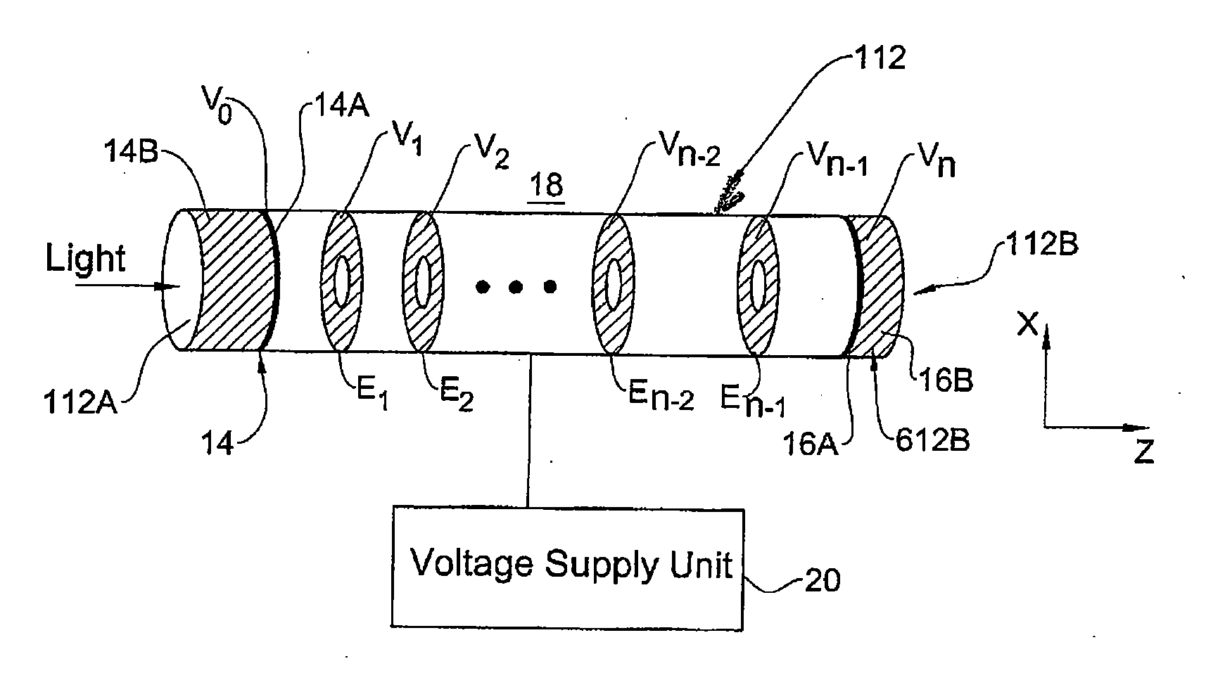
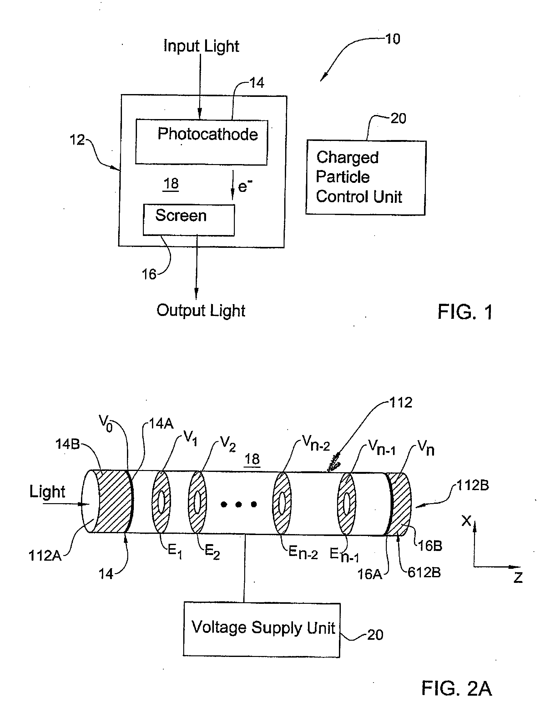
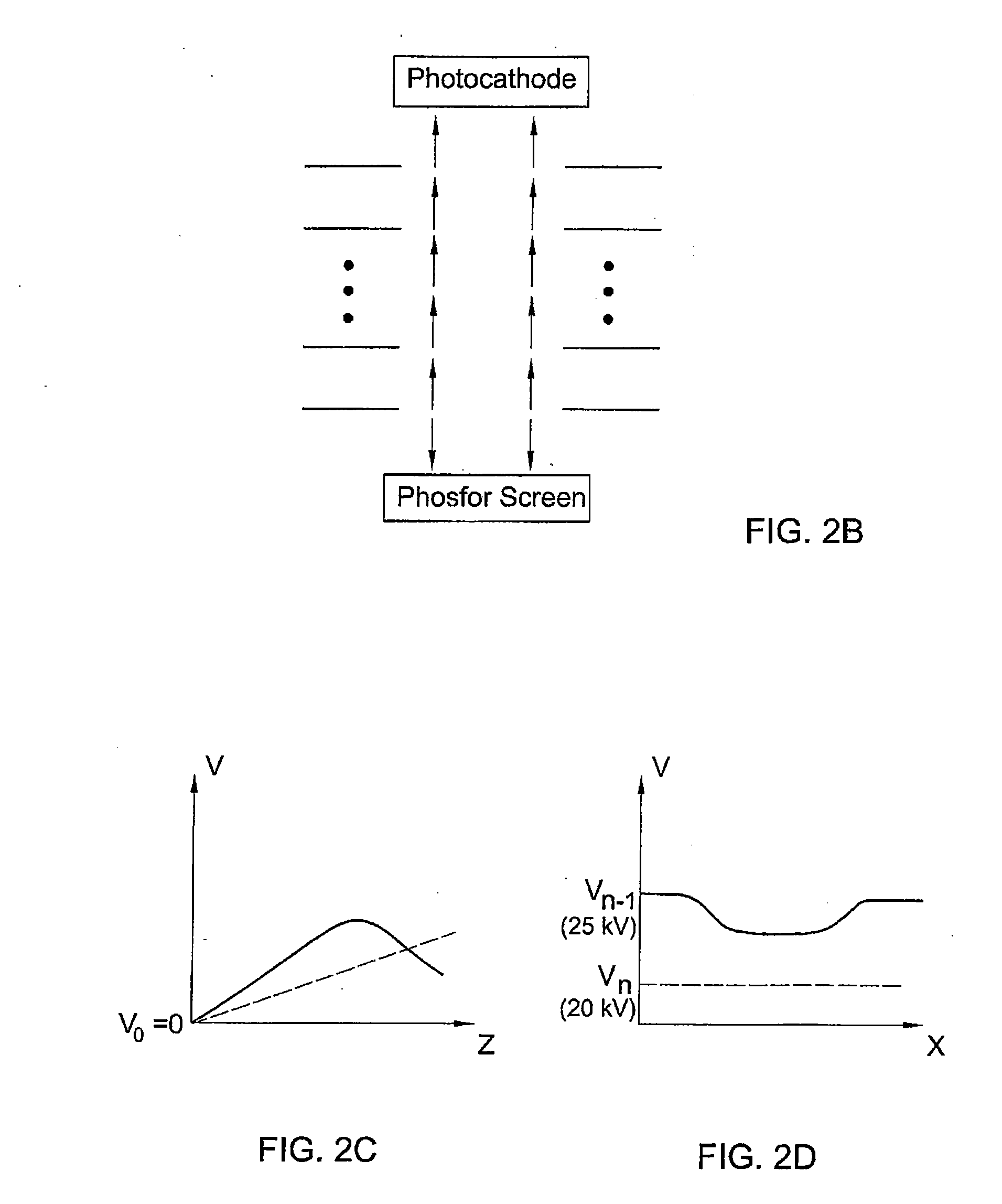
[0030] Referring to FIG. 1, there is illustrated by way of a block diagram an example of an image intensifier device 10 of the present invention. Image intensifier device 10 is configured as a magnetically focused “first generation image intensifier” device, namely includes a vacuum tube 12 including spaced-apart photocathode unit 14 (for example including a multialkali photocathode layer) and a luminescent screen unit 16 accommodated in a magnetic field region 18. Photocathode unit 14 has an active region exposed to input light to convert the input light into emitted electrons propagating through the vacuum tube and hitting the luminescent screen unit, thereby causing an intensified light output therefrom. Typically, the luminescent screen consists of a phosphor layer having a backing layer of aluminum. Typically, the electrons-to-light conversion at the phosphor screen originates ions.

[0031] Device 10 of the present invention is configured to define a charged particle control mec...


PUM


Abstract

An image intensifier device includes a photocathode unit having an active region adapted to convert light to electrons; a luminescent screen unit adapted to convert electrons emitted from the photocathode unit to light while generating ions; and a charge particle control unit. The latter is adapted to direct electrons from the photocathode unit towards the luminescent screen unit while substantially preventing the generated ions to reach at least the active region of the photocathode unit.

Description

RELATED APPLICATION [0001] This application is a NONPROVISIONAL of, claims priority to and incorporates by reference U.S. Provisional Patent Application 60 / 715,900, filed 8 Sep. 2005.FIELD OF THE INVENTION [0002] This invention relates to image intensifiers, and particularly to magnetically focused image intensifiers. BACKGROUND [0003] Image intensifiers are widely used for sensing and amplifying, or intensifying, light images of low intensity. In these devices, light (usually of visible or near infra-red spectra) from an associated optical system is directed onto a photocathode which emits a distribution of photoelectrons in response to the input radiation. [0004] Image intensifiers typically include a vacuum tube with a photocathode at one end and a phosphor screen at the other end, the photocathode converts incoming photons to electrons which are accelerated by an electric filed (potential difference) in the tube until they hit the phosphor screen converting them back to photons....

Claims


Application Information

Patent Timeline
IPC IPC(8): H01J43/30H01J31/50
CPCH01J31/501
Inventor KUZNIZ, TALPINKAS, IDDO
Owner APPL MATERIALS ISRAEL LTD
Why Eureka
Try Eureka