Power Supply Apprartus

a power supply and apprartus technology, applied in the direction of electric variable regulation, process and machine control, instruments, etc., can solve the problems of power loss in the regulator or the ballast resistor, system cost to be realized as an integrated circuit, numerous prior art deficiencies, etc., to improve efficiency, improve efficiency, and reduce power loss during the charging phase

Inactive Publication Date: 2007-03-08
NG SHEKWAI
View PDF5 Cites 21 Cited by
  • Summary
  • Abstract
  • Description
  • Claims
  • Application Information

AI Technical Summary

Benefits of technology

[0014] An advantage of the present invention is that it provides an efficient, automatically operating transitioning system for multiple mode operation of a charge pump, one able to accommodate a full range of charge pump input conditions and output loads. When a gain of 4 / 3 can be selected, there is an 11% improvement in efficiency over the use of a gain of 3 / 2. When a gain of 5 / 3 can be selected, there is a 17% improvement in efficiency over the use of a gain of 2.
[0015] Another advantage of the present invention is that it may be largely monolithically implemented. The invention may be incorporated into monolithic integrated circuit type charge pump designs without the need for additional discrete components or resorting to non-monolithic assemblies. The layout of the switches in an integrated circuit incurred no extra area in comparison with prior arts which have gains of 1, 3 / 2 and 2 only because the same number of switches is used. Hence the present invention is commercially viable. Yet the invention may also use discrete components or non-monolithic assemblies, or be integrated into charge pump designs which use such for other purposes, if a designer so wishes.
[0016] Another advantage of the present invention is that a switch between two of the three capacitors is eliminated. Thus, the power loss during the charging phase is smaller and the efficiency of the present invention is further improved over the prior art without penalty.
[0017] Another advantage of the present invention is that the maximum voltage inside the circuit is still within the operational limit of digital integrated circuits such that the circuit may be implemented using widely understood and economical integrated circuit digital logic process.
[0018] Another advantage of the present invention is that the mode transition is always optimum for all range of input voltage and load current and load voltage and tolerance in all elements.
[0019] These and other objects and advantages of the present invention will become clear to those skilled in the art in view of the description of the best presently known mode of carrying out the invention and the industrial applicability of the preferred embodiment as described herein and as illustrated in the several figures of the drawings.

Problems solved by technology

Therefore, power is lost in the regulator or the ballast resistor.
However, there are numerous deficiencies in these prior arts.
This renders the system expensive to be realized as an integrated circuit because the wires needed to connect all switches and capacitors will occupy too much area.
Hence the charge pump in U.S. Pat. No. 6,055,168 is not an appropriate commercial LED backlight power supply solution because the extra efficiency does not justify the extra cost incurred.
When the actual load current is bigger than the assumed value, the switchover will be too late.
Therefore the worst cases, largest load current and worst manufacturing tolerance, must be assumed and thus the efficiency of the power supply cannot be optimum for all range of load current and battery voltage.

Method used


Image

  • Power Supply Apprartus
  • Power Supply Apprartus
  • Power Supply Apprartus

Examples


first embodiment

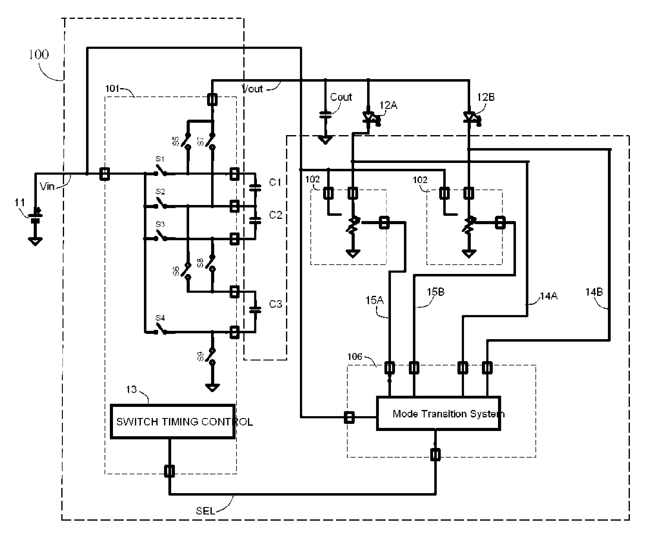
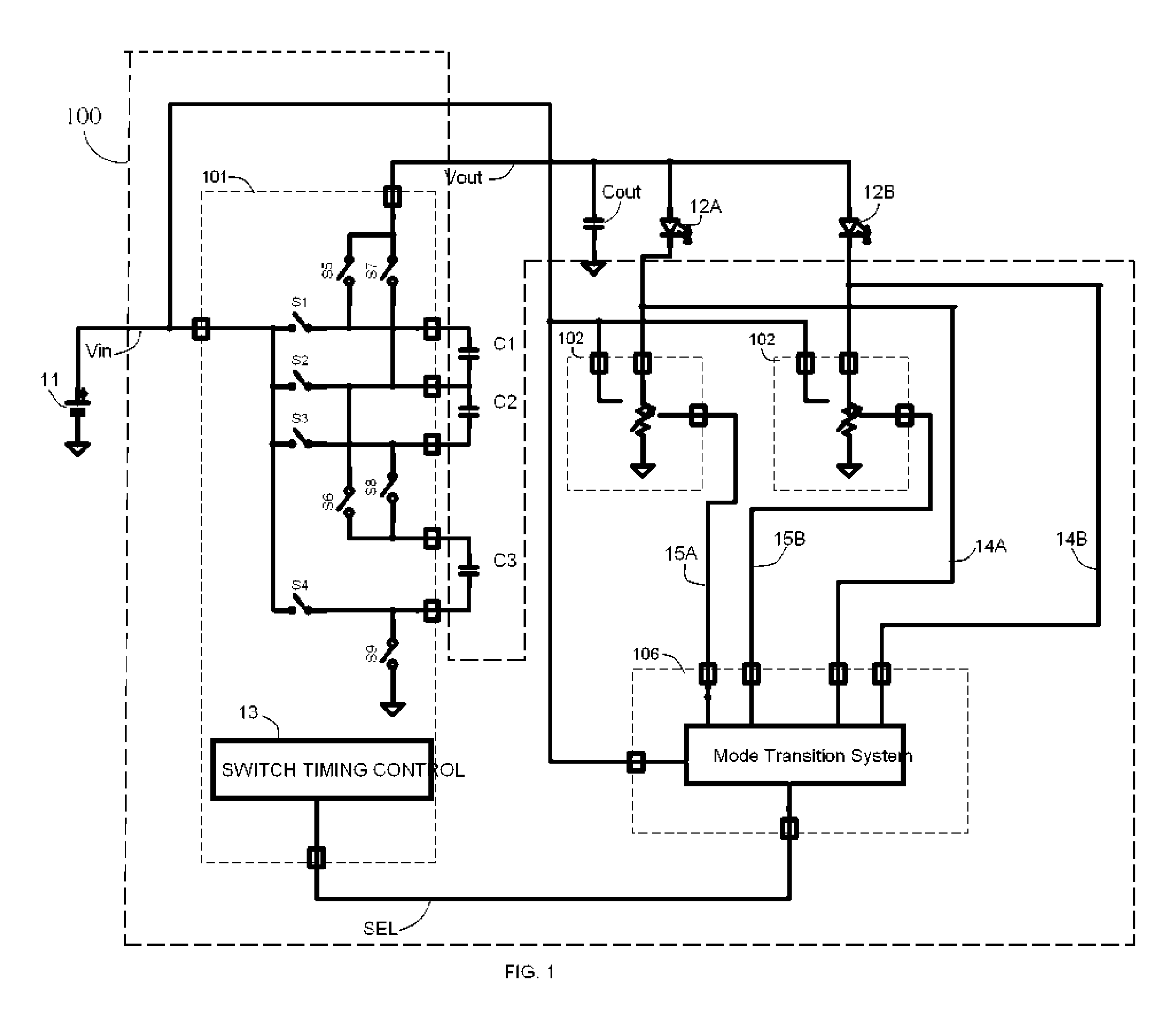
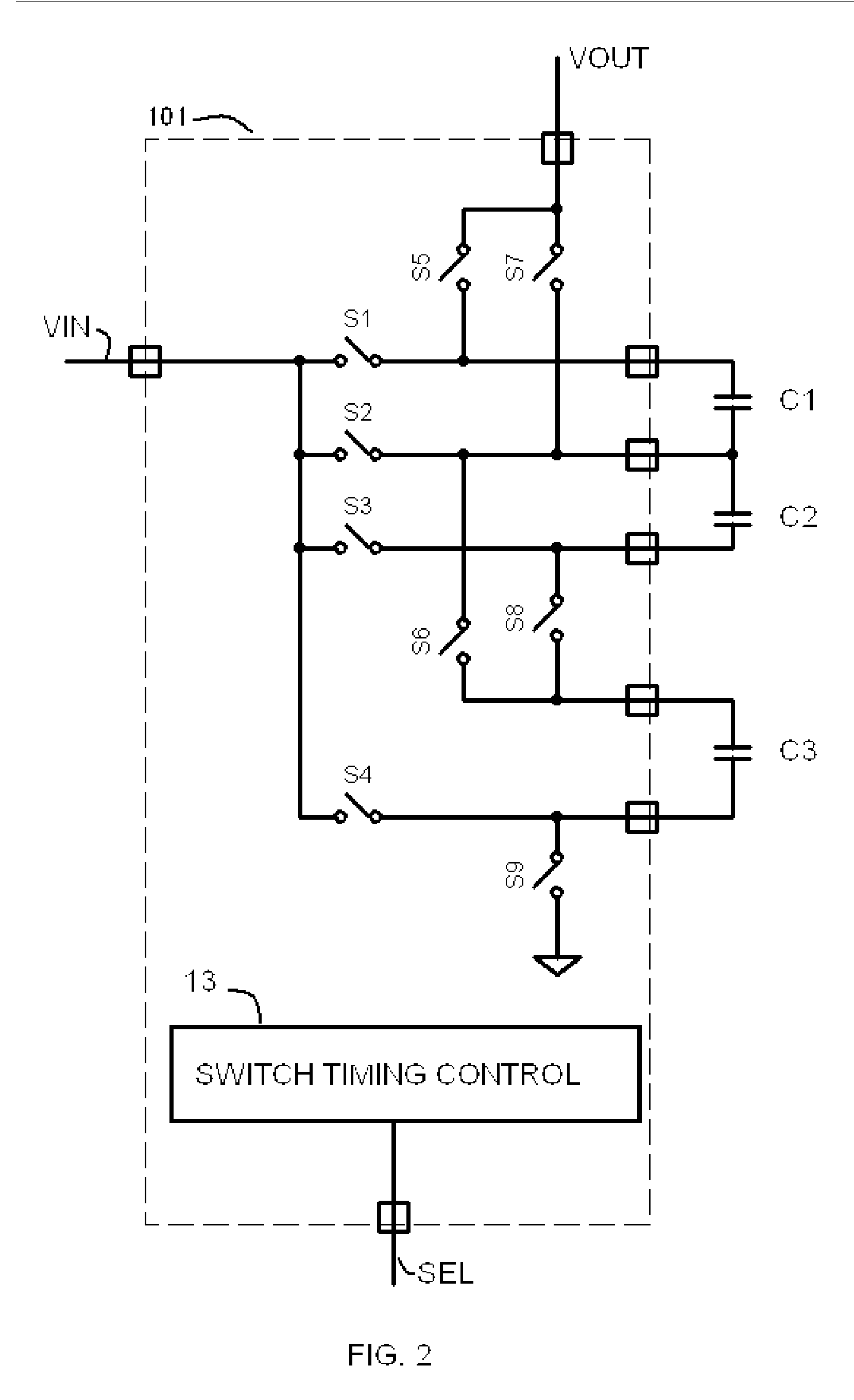
[0045]FIG. 2 illustrates a structure of a charge pump circuit 101 according to the present invention. The charge pump circuit 101 boosts an input voltage Vin to an output voltage Vout by performing ON / OFF control of switches S1 to S9 according to a preset timing sequence and thereby switching both the connection mode and the timing of charging or discharging of three boosting capacitors C1, C2 and C3. The timing sequence is provided by the switch timing control sub-system 13 according to the mode selection signal SEL.

[0046]FIG. 3 illustrates ON / OFF states of switches S1 to S9 when the gain is 1. As it is shown in FIG. 3, S4 and S9 are each placed in the OFF position and the other switches in the ON position, so that the input voltage Vin is outputted just as it is as the output voltage Vout.

[0047] Next, the case where the gain is 4 / 3 times is explained below. FIG. 4A, FIG. 4B and FIG. 4C illustrates ON / OFF states of switches S1 to S9 during the charging and discharging phases.

[004...

second embodiment

[0065]FIG. 13 illustrates a charge pump circuit 101 in FIG. 1 when only the gains (1; 4 / 3; 3 / 2; 2) are needed. Switch S6 is connected between the terminal VOUT and a pin of C3. This will improve the efficiency of the charge pump circuit because the current from C3 can be passed to the output directly without passing through S7.

[0066]FIGS. 14-17 illustrate ON / OFF states of S1 and S9 and charging and discharging sequences of the charge pump circuit 101 in FIG. 13 for the gain of 4 / 3, 3 / 2, and 2 respectively. FIGS. 13-16 can be analyzed and understood in the same manner as the explanation for FIG. 4 above and should be obvious to those who are skilled in the art.

[0067] The present invention has been described based on the embodiment above is only exemplary. It is therefore understood by those skilled in the art that there exists other various modifications to the combination of each component and process described above and that such modifications are also encompassed by the scope of ...


PUM


Abstract

The invention relate to a power supply apparatus operating on the charge pump principle, comprising multiple regulators and three boosting capacitors switched in a switch matrix consisting of nine switches. A control circuit is provided capable of controlling the switches so that the charge pump is changed over between charging phases and discharge phases and which is capable of operating the charge pump in different voltage gains (1; 4/3; 3/2; 5/3; 2). The invention comprises furthermore a mode transitioning system. The selection of a mode is based on comparators capable of comparing signals from current regulation elements to predetermined voltages and then when the former attains the latter, changing over the charge pump into the corresponding other mode, wherein the predetermined voltages are selected so that the efficiency of the converter is optimized.

Description

FIELD OF INVENTION [0001] The present invention relates generally to charge pump power supplies for electronic systems, and more particularly to a high efficiency charge pump and its operation, which are commonly used in such power supplies, by controlling the transitioning of such charge pumps between multiple modes of operation. BACKGROUND OF INVENTION [0002] In many portable electronic products, LED (Light Emitting Diode) elements are used as backlight for an LCD (Liquid Crystal Display) or a flash light for the attached camera and a battery is used as the power source. To drive the LED elements, the battery voltage, ranged from 3V-4.2V, must be stepped up to the LED voltage, ranged from 3.0V-4V. A charge pump circuit is commonly used as a power supply apparatus to provide the step up function. Because of the fixed step-up gain of a charge pump, the output voltage is always higher than the necessary drive voltage. Therefore, a regulator or ballast resistor is needed to adjust the...

Claims


Application Information

Patent Timeline
Patent Type & Authority Applications(United States)
IPC IPC(8): G05F1/10
CPCH02M3/07Y02B70/1491H02M2001/0054Y02B70/10H02M1/0054
Inventor NG, SHEKWAI
Owner NG SHEKWAI
Why Eureka
Try Eureka