In-plane switching liquid crystal display

a liquid crystal display and in-plane switching technology, applied in non-linear optics, instruments, optics, etc., can solve the problems of small viewing angle and non-uniform display, disadvantageous ips lcd in lower aperture ratio and color shift, and achieve low production cost and high aperture ratio

Active Publication Date: 2007-03-08
HANNSTAR DISPLAY CORPORATION
View PDF8 Cites 59 Cited by
  • Summary
  • Abstract
  • Description
  • Claims
  • Application Information

AI Technical Summary

Benefits of technology

[0009] It is an aspect of the present invention to provide an in-plane switching liquid crystal display with a low production cost and a high aperture ratio.

Problems solved by technology

However, there are still some problems for the LCD needed to be improved and solved, such as the small viewing angle and the non-uniform displaying.
It is known that, however, the IPS LCD is disadvantageous in lower aperture ratio and color shift.
However, such a structure of the S-IPS LCD still needs to be improved since it is difficult to suppress the local crosstalk caused by the capacitive coupling between the pixel electrodes 114 and the data lines 112.
However, the application of the overcoat layer results in a significant increase in the manufacturing cost.

Method used


Image

  • In-plane switching liquid crystal display
  • In-plane switching liquid crystal display
  • In-plane switching liquid crystal display

Examples


first embodiment

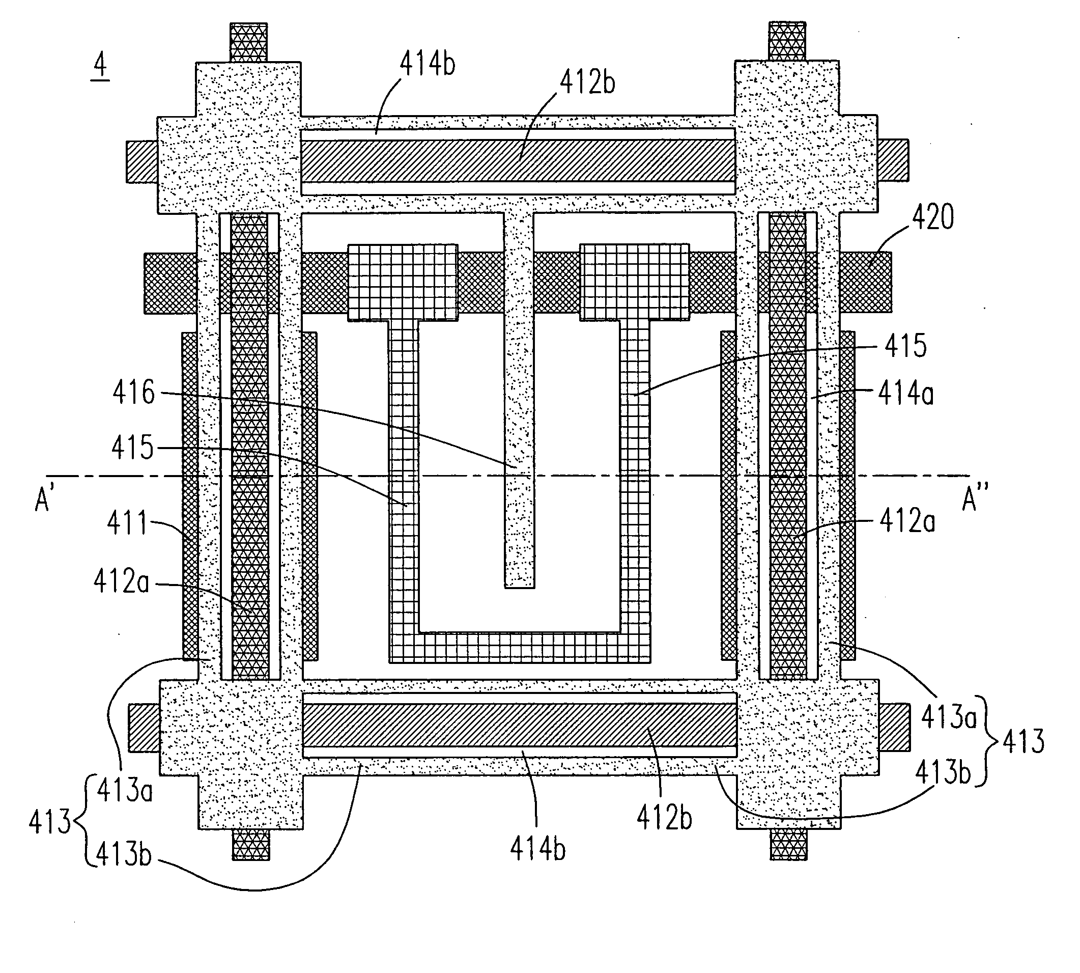
[0053] Please refer to FIGS. 4A and 4B, which are respectively the plan view and the cross-sectional view schematically showing the in-plane switching liquid crystal display according to the present invention. The advanced super-no overcoat liquid crystal display (AS-NOOC LCD) 4 includes a first substrate 41 and a second substrate 42 that are faced to each other. On the first substrate 41, as shown in FIG. 4A, a plurality of electrodes including the shielding electrodes 411, the data lines 412a as well as the gate lines 412b and the first portion 413 (413a , 413b ) of the common electrode are disposed. In more specific, each of the data lines 412a is positioned above and between the respective pair of shielding electrodes 411, and each of the first portion 413 of the common electrode has a first slit 414a and a second slit 414b whose positions are respectively corresponding to the data line 412a and the gate line 412b therebelow. Moreover, the first slit 414a and the second slit 414...

second embodiment

[0058] As an alternative, a counter electrode made of a transparent material is also preferred. Please refer to FIG. 5, which is the cross-sectional view schematically showing the in-plane switching liquid crystal display according to the present invention. In this embodiment, the transparent counter electrodes 521 are applied with a fixed voltage or a common voltage for shielding the electric field of the data lines. In order to prevent the light leakage, a BM resin 522 is applied to the second substrate 52, and thereon the color layer 56 and the second passivation layer 57 are arranged in turns. The transparent counter electrodes 521 are disposed and corresponding to the respective data lines on the first substrate.

third embodiment

[0059] As a further alternative, the transparent counter electrode is covered with a passivation layer so as to be protected from the moisture. Please refer to FIG. 6, which is the cross-sectional view schematically showing the in-plane switching liquid crystal display according to the present invention. In this embodiment, the transparent counter electrodes 621 are applied directly on the color layer 66, and are covered with a second passivation layer 67, so that a further protection for the counter electrodes 621 is achievable.

[0060] In addition to the arrangement of the counter electrode on the second substrate, the present invention is further advantageous in the various configuration and combination of the electrodes disposed on the first substrate. With reference to FIG. 4A, the first portion 413 of the common electrode is formed by the first portions 413a and 413b running in different directions that are corresponding to the data line 412a and the gate line 412b , respectivel...


PUM

PropertyMeasurementUnit
horizontal distanceaaaaaaaaaa
vertical distanceaaaaaaaaaa

Abstract

An in-plane switching liquid crystal display, especially relative to an in-plane switching liquid crystal display with the absence of an overcoat layer is provided. The in-plane switching liquid crystal display having a first substrate, a second substrate and a liquid crystal layer sandwiched therebetween, a plurality of gate lines and data lines disposed on the first substrate, a counter electrode disposed on the second substrate and corresponding to one of the data lines, a pixel having a pixel electrode, a pair of shielding electrodes and a common electrode also disposed on the first substrate. Through the arrangement of shielding electrodes as well as the counter electrode, the coupling effect of the applied pixel voltage on the data lines is shielded.

Description

FIELD OF THE INVENTION [0001] The present invention relates to a liquid crystal display (LCD), and more particularly to an in-plane switching (IPS) LCD. BACKGROUND OF THE INVENTION [0002] The liquid crystal display (LCD) has been broadly used in various applications in the daily life with the improvement and popularity of the digital network technology. Nowadays, the image quality of the LCD is nip and tuck with that of the cathode ray tube (CRT) display. However, there are still some problems for the LCD needed to be improved and solved, such as the small viewing angle and the non-uniform displaying. [0003] Many techniques are developed for obtaining a wider viewing angle for the LCD, among which the in-plane switching (IPS) mode is regarded as an excellent technique to achieve the mentioned purpose. It is known that, however, the IPS LCD is disadvantageous in lower aperture ratio and color shift. In order to resolve the color shift of the IPS LCD, various improved LCD structures, ...

Claims


Application Information

Patent Timeline
Patent Type & Authority Applications(United States)
IPC IPC(8): G02F1/1343
CPCG02F1/134363G02F2201/121G02F2001/136218G02F1/136218
Inventor LIN, JIUNN-SHYONGSHIH, PO-SHENGYANG, KEI-HSIUNGLIAO, TAI-SHUN
Owner HANNSTAR DISPLAY CORPORATION
Why Eureka
Try Eureka