
Alternate combustion type regenerative radiant tube burner apparatus

Inactive Publication Date: 2007-03-08
NIPPON FURNACE KOGYO KAISHA LTD +1
View PDF6 Cites 18 Cited by
  • Summary
  • Abstract
  • Description
  • Claims
  • Application Information

AI Technical Summary

Benefits of technology

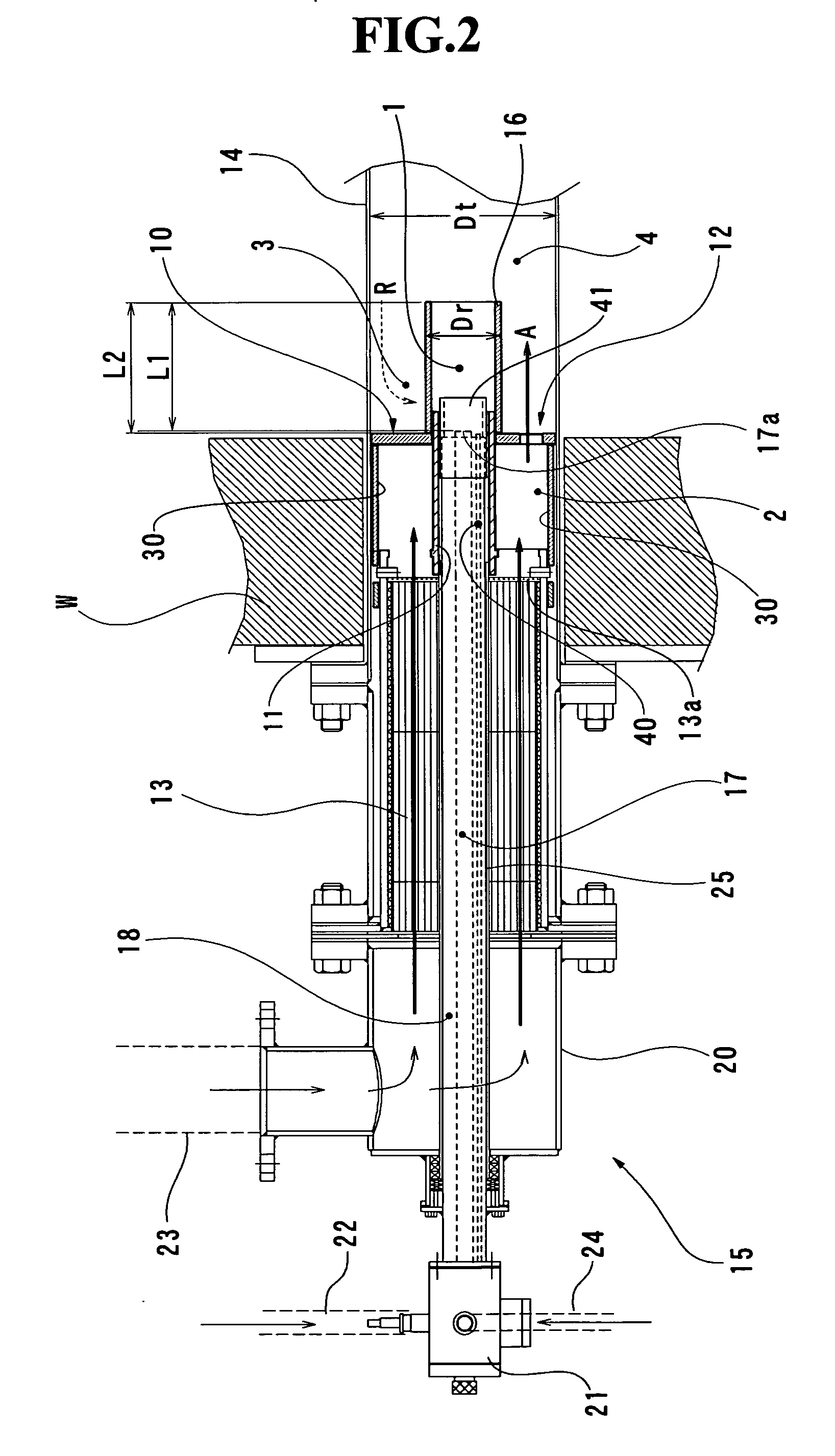
[0007] The present inventors have found that the concentration of nitrogen oxides in the combustion exhaust gas can be definitely prevented from increasing, by fully blocking the secondary combustion air flowing through a peripheral edge portion of the circular plate to the main combustion chamber. The present inventors have attained the object of the invention as set forth above, based on such findings.

Problems solved by technology

Therefore, loss of the total pressure in the burner apparatus increases, so that a large capacity of intake blower and a large capacity of exhaust blower have to be installed in many cases.
It has been found that such increase in the concentration of nitrogen oxides is also caused by thermal deformation of a tube portion.

Method used


Image

  • Alternate combustion type regenerative radiant tube burner apparatus
  • Alternate combustion type regenerative radiant tube burner apparatus
  • Alternate combustion type regenerative radiant tube burner apparatus

Examples


Embodiment Construction

[0044] With reference to the attached drawings, a preferred embodiment of the present invention is described hereinafter.

Structure of Burner Apparatus

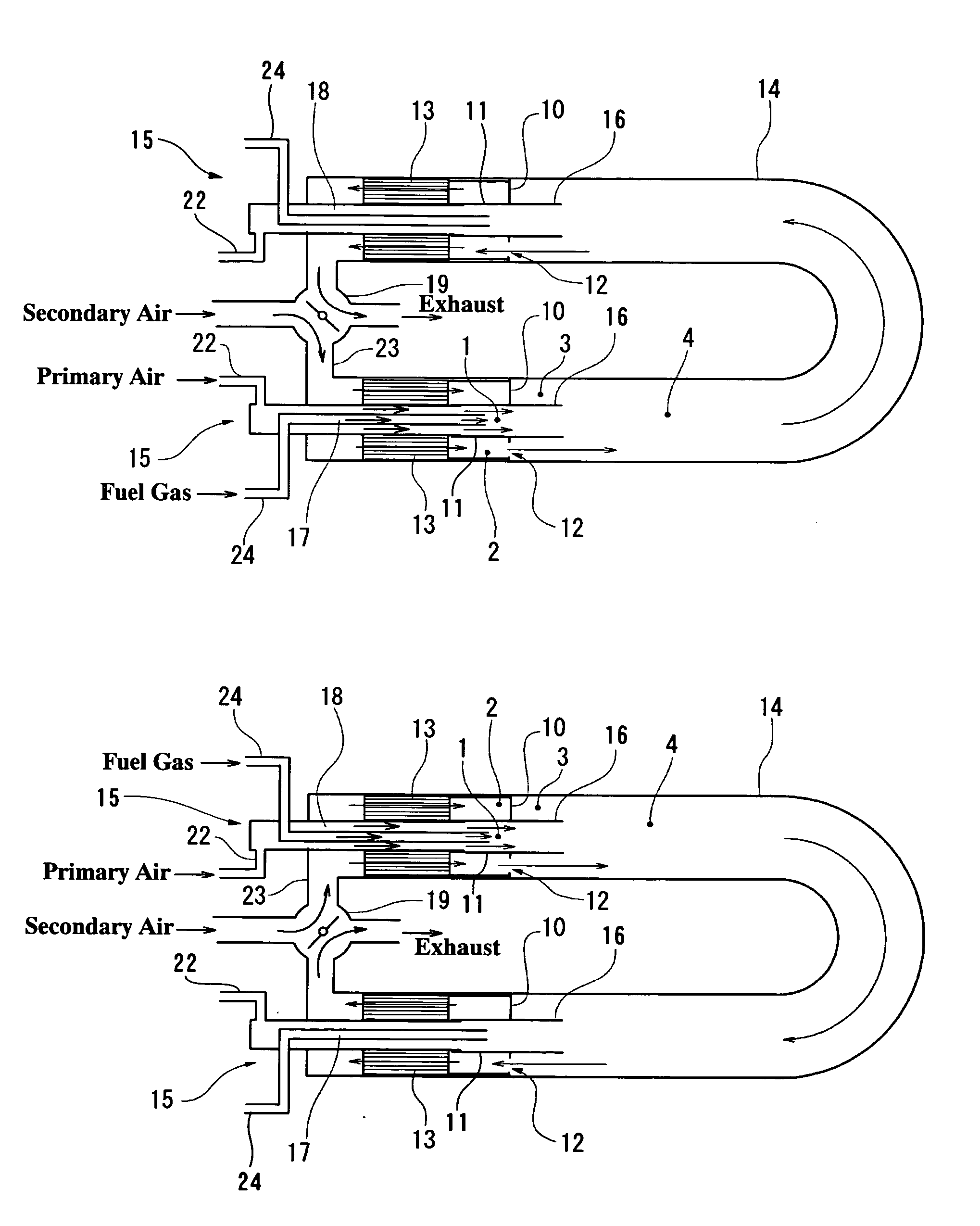
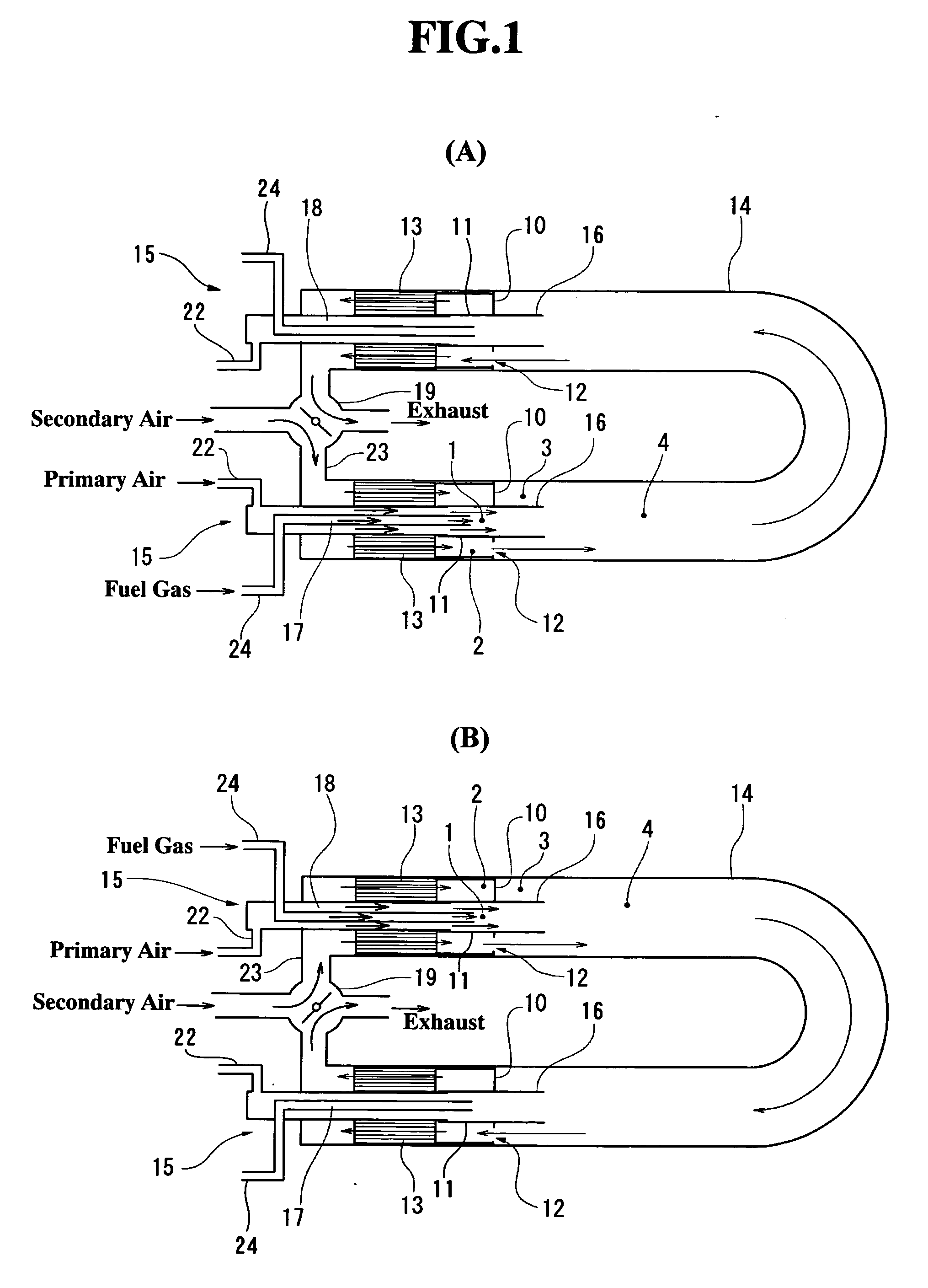
[0045] As shown in FIG. 1, an alternate combustion type regenerative radiant tube burner apparatus (referred to as “burner apparatus” hereinafter) has a radiant tube 14 forming a main combustion chamber 4. Burner units 15 are provided on both end portions of the tube 4. A four-way valve 19 is connected with the respective burner units 15 so that each of the burner units 15 is selectively connected to either an air supply system or an exhaust system. Each of the burner units 15 is provided with a ceramic regenerator 13 having a honey-comb structure. A fuel feed passage 17 and a primary air passage 18 of the burner unit 15 extend through the regenerator 13. The burner units 15 in a pair are alternately changed over to either an operation mode as shown in FIG. 1(A) or an operation mode as shown in FIG. 1(B) at predetermined time interv...


PUM


Abstract

The present invention relates to an alternate combustion type regenerative radiant tube burner apparatus which comprises a circular plate positioned between a burner unit and a main combustion chamber, so that preheated secondary combustion air is fed through an opening of the circular plate to the main combustion chamber. The burner apparatus has the circular plate (10), an annular air throat (2), a cylindrical peripheral cover (30) and a heat-transfer tube (11,16). A front end portion of the peripheral cover is integrally connected with a peripheral edge portion of the circular plate so as to prevent the secondary combustion air of the air throat from leaking on a periphery of the circular plate to the air diluting chamber (3). According to the present invention, the concentration of nitrogen oxides in the combustion exhaust gas can be definitely prevented from increasing, without being affected by the installation condition or thermal deformation of the radiant tube burner apparatus.

Description

TECHNICAL FIELD OF THE INVENTION [0001] The present invention relates to an alternate combustion type of regenerative radiant tube burner apparatus, and more particularly, to such an apparatus which has a circular plate positioned between a burner unit and a combustion chamber so that preheated secondary combustion air is fed through an opening of the plate to the combustion chamber. BACKGROUND OF THE INVENTION [0002] A radiant tube burner apparatus indirectly heating an inside atmosphere of a furnace is practically in use as heating means of a heating furnace for steel, furnace for heat treatment, and so forth. As a kind of the radiant tube burner apparatus, the alternate combustion type regenerative radiant tube burner apparatus is known in the art, in which regenerators of honey-comb structures are provided on both end portions of a radiant tube (Japanese patent laid-open publications Nos. 8-247421, 11-108315, 11-108316, and U.S. patent publication No. 6,027,333). [0003] Conventi...

Claims


Application Information

Patent Timeline
IPC IPC(8): F23C5/08F23C3/00F23D14/22F23L15/02
CPCF23C3/002F23L15/02F23D14/22Y02E20/34F23C13/00F24H1/0045F24H1/41F23D2213/00
Inventor TADA, TAKESHIMOCHIDA, SUSUMUKITAHARA, SHINYAFUKUSHIMA, SHINICHIROSUZUKAWA, YUTAKASUGA, MASAHARUMORI, ISAOOISHI, HITOSHIISHIOKA, MUNEHIROHASEGAWA, TOSHIAKI
Owner NIPPON FURNACE KOGYO KAISHA LTD
Learn More