Cooling device

a cooling device and cooling technology, applied in the direction of machines, lighting and heating apparatus, transportation and packaging, etc., can solve the problems of increasing ambient temperature, reducing the efficiency of cooling device, and large energy consumption of hot water supply, so as to achieve enhanced energy consumption efficiency of the whole cooling device, the effect of reducing energy consumption and reducing energy consumption

Inactive Publication Date: 2007-03-15
PANASONIC INTELLECTUAL PROPERTY MANAGEMENT CO LTD
View PDF11 Cites 23 Cited by
  • Summary
  • Abstract
  • Description
  • Claims
  • Application Information

AI Technical Summary

Benefits of technology

[0005] The present invention has been developed to solve the problem of such a conventional technology, and an object thereof is to provide a highly efficient cooling device which is capable of reducing energy consumption.
[0025] Furthermore, in a case where the hot water is generated simultaneously with the cooling, and this hot water is used for the cleaning or the like, a preferred highly efficient run is possible. In consequence, energy consumption efficiency of the whole cooling device can be enhanced, and energy consumption can be reduced.

Problems solved by technology

However, in the above cooling device, there has been a problem that since hot water necessary for the cleaning is supplied from a boiler, an electric water heater or the like, energy consumption for the supply of the hot water is large.
Furthermore, since heat generated by the condensation of the refrigerant is released to the atmosphere from the condenser having the refrigeration cycle, effective utilization of the energy is not realized.
There is also a problem that a rise in ambient temperature is brought about.

Method used


Image

  • Cooling device
  • Cooling device
  • Cooling device

Examples


example 1

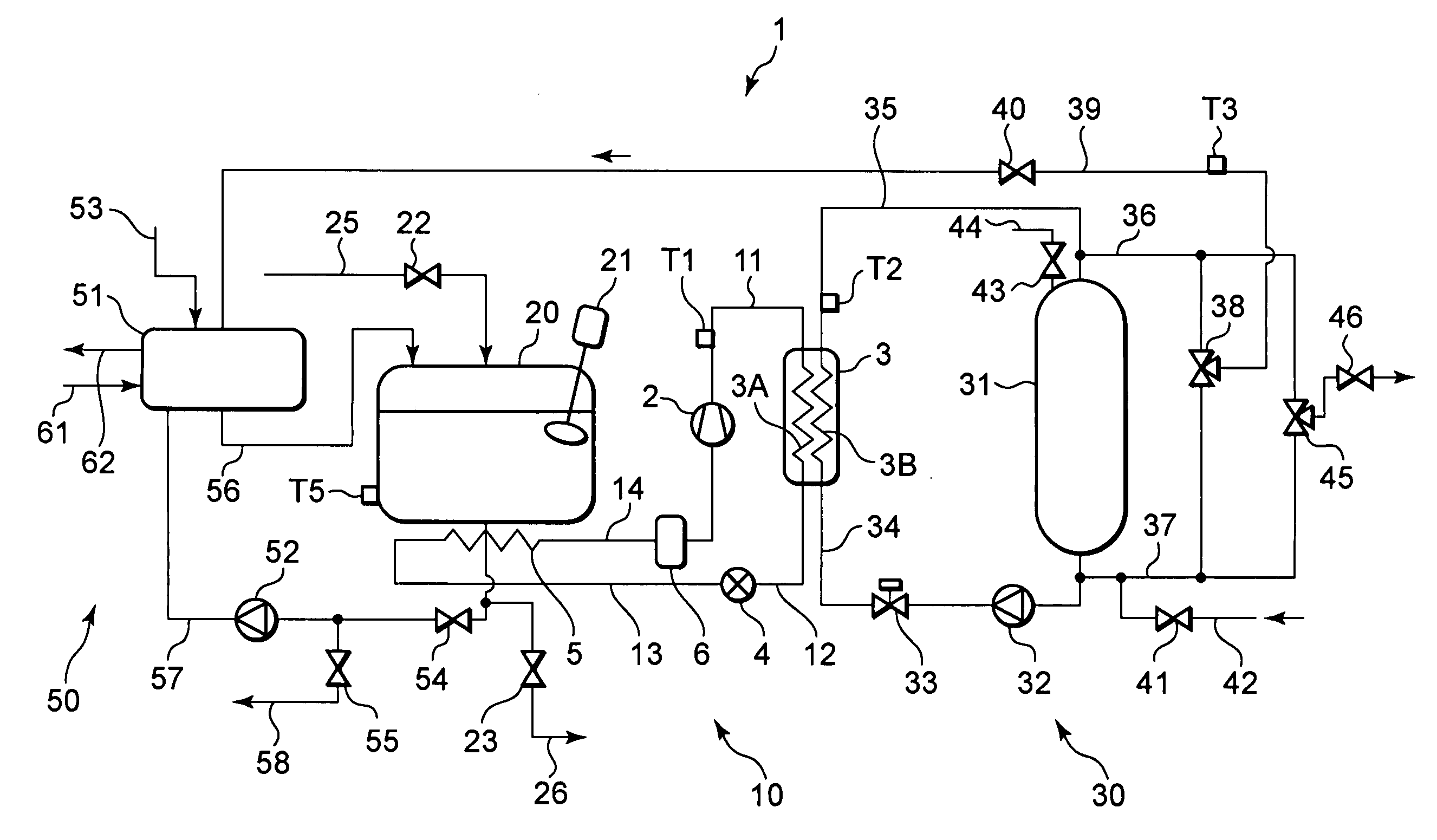
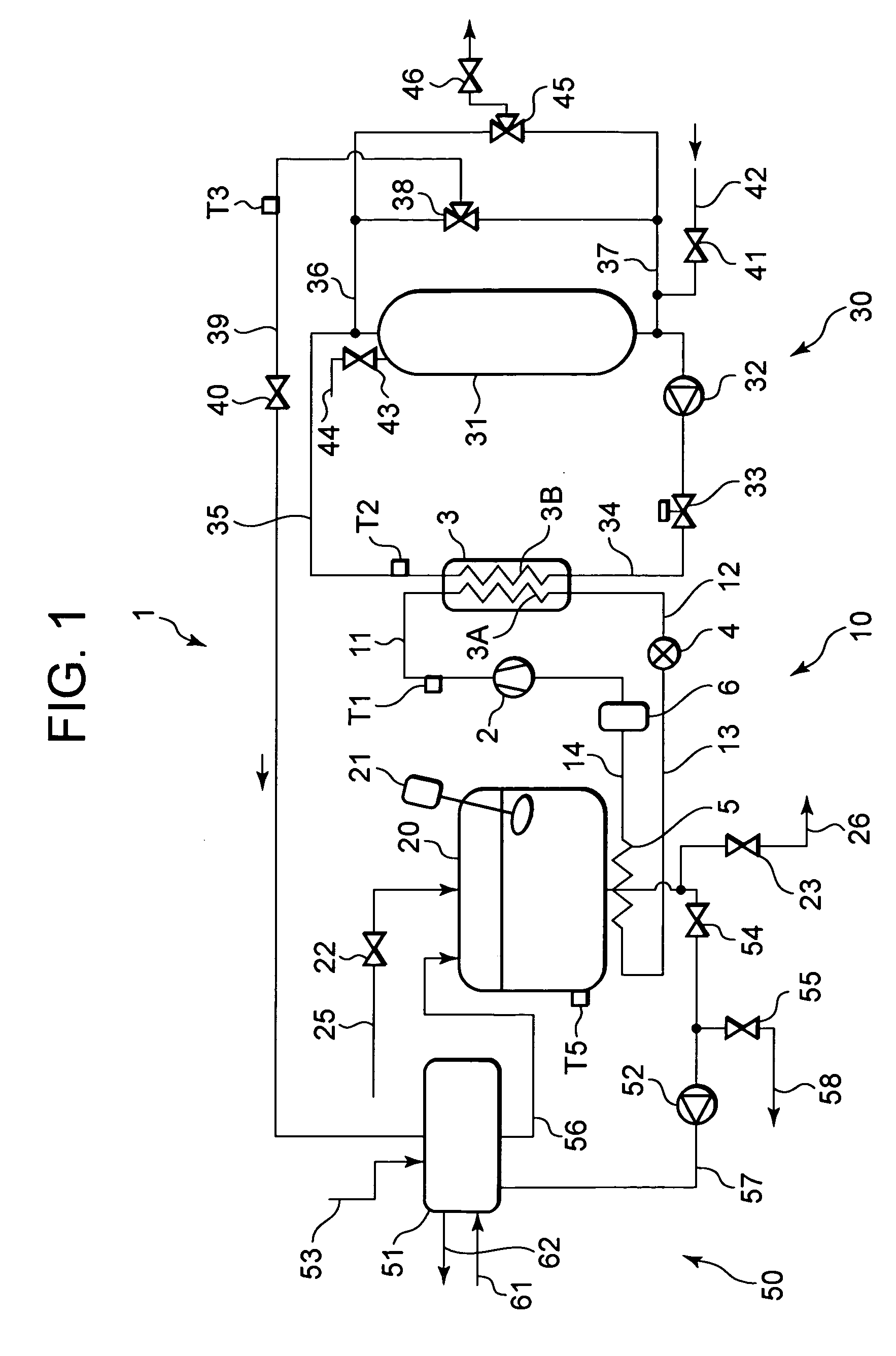
[0046]FIG. 1 is a circuit diagram of a cooling device 1 in a first example of the present invention. The cooling device 1 of the present example includes a refrigeration cycle circuit 10, a hot water supply circuit 30, a cooling container 20 and an automatic cleaning circuit 50.

[0047] The refrigeration cycle circuit 10 is constituted so that a compressor 2, a discharge pipe 11, a radiator 3A, a high-pressure refrigerant pipe 12, an expansion valve 4 as throttle means, a low-pressure refrigerant pipe 13, an evaporator 5 and a suction tube 14 are successively connected to one another to form a closed circuit. Here, the radiator 3A is included in a water heat exchanger 3, the water heat exchanger 3 includes a refrigerant channel 3A (radiator 3A) on a refrigeration cycle circuit 10 side and a water channel 3B on a hot water supply circuit 30 side, and the refrigerant channel 3A is heat-exchangeably connected to the water channel 3B so that a refrigerant counters a water stream.

[0048] ...

example 2

[0120] A second example will be described as another embodiment of the present invention. A basic constitution of Example 2 is similar to that of the cooling device 1 of Example 1 shown in FIG. 1. The present example is different from the first example in that an evaporator 152 shown in FIG. 9 is disposed instead of the evaporator 5.

[0121] The evaporator 152 is constituted of a header tube 5H constituted by working a round tube made of copper; and a plurality of heat transfer tubes 5C similarly made of copper. The heat transfer tubes 5C are bonded to the header tube 5H so that a refrigerant flows through the heat transfer tubes. The header tube 5H is bonded to a low-pressure refrigerant pipe 13 into which the refrigerant flows, and a suction tube 14 out of which the refrigerant flows.

[0122] In the header tube 5H, partitions which interrupt the flow of the refrigerant can be arranged if necessary. Accordingly, it is possible to set, to predetermined values, the number of paths thro...

example 3

[0126] Example 3 will be described as still another embodiment of the present invention. A basic constitution of Example 3 is similar to that of the cooling device 1 of Example 1 shown in FIG. 1. The present example is different in that instead of the evaporator 5, an evaporator 153 shown in FIG. 10 is disposed. It is to be noted that FIG. 10A is a plan view of the evaporator 153, and FIG. 10B is a bottom plan view of the evaporator 153. FIG. 11 shows a sectional view of the evaporator 153 cut along the A-A line of FIG. 10. In the evaporator 153, as shown in FIG. 11, a flat tube having a plurality of small-diameter holes 5A constituting refrigerant channels of a refrigeration cycle circuit 10 is constituted as a heat transfer tube 153C, and a header tube 5H is bonded so as to communication with the small-diameter holes 5A of the heat transfer tube 153C and form the refrigerant channels.

[0127] The header tube 5H is provided with a refrigerant inlet portion into which a refrigerant f...


PUM


Abstract

There is disclosed a highly efficient cooling device which can reduce energy consumption, and the cooling device comprises: a refrigeration cycle circuit including a compressor, a radiator, an expansion valve and an evaporator; a cooling container in which a cooling object is stored; and a hot water storage tank which stores hot water. Moreover, the cooling object in the cooling container is cooled by absorption of heat in the evaporator, water is boiled by release of the heat in the radiator to store the hot water in the hot water storage tank, and the hot water in the hot water storage tank can be supplied into the cooling container.

Description

BACKGROUND OF THE INVENTION [0001] The present invention relates to a cooling device including cooling means for cooling a cooling object stored in a cooling container, and taking out this cooling object to thereafter clean or sterilize the cooling container or the like. [0002] In general, as a method of cooling a cooling object such as food to store the object, there is broadly utilized a cooling device using a vapor compression type refrigeration cycle. In this type of cooling device, the cooling object is cooled by an evaporation function of a refrigerant in an evaporator, and heat is released to the atmosphere or the like owing to condensation of the refrigerant in a condenser. In Japanese Patent No. 2860352, there is disclosed a method in which milk immediately after drawn is introduced into a milk tank to cool the milk by a freezer. [0003] Moreover, in a device which handles the food and the like, for a hygienic reason, it is important to clean and sterilize the device. Even i...

Claims


Application Information

Patent Timeline
Patent Type & Authority Applications(United States)
IPC IPC(8): B60H1/32
CPCA01J9/04F25B9/008F25B29/003F25B2700/21171F25B47/00F25B2309/061F25B2400/24F25B39/02
Inventor OTAKE, MASAHISASATO, KOJIMUKAIYAMA, HIROSHI
Owner PANASONIC INTELLECTUAL PROPERTY MANAGEMENT CO LTD
Why Eureka
Try Eureka