Control apparatus for internal combustion engine

a control apparatus and internal combustion engine technology, applied in electrical control, machines/engines, non-mechanical valves, etc., can solve the problems of deterioration of exhaust emission, degrading drivability or deteriorating exhaust emission, and affecting the operation of the control apparatus, so as to increase the lift of the intake valve 29 and increase the amount of fuel sucked into the cylinder. , the effect of increasing the amount of fuel

Inactive Publication Date: 2007-03-15
DENSO CORP
View PDF10 Cites 5 Cited by
  • Summary
  • Abstract
  • Description
  • Claims
  • Application Information

AI Technical Summary

Benefits of technology

[0059] Thus, when the variable intake valve lifter 30 is switched from low lift mode to high lift mode to increase the amount of lift of the intake valve 29, the injection quantity is corrected and increased. Therefore, even though the amount of lift of the intake valve 29 is increased, the valve closing timing of the intake valve 29 is delayed, and the back flow of rich gas in the cylinder is increased (i.e., the residual volume of rich gas in the cylinder is reduced), the injection quantity can be corrected and accordingly increased to increase the quantity of fuel sucked into the cylinder. Also, the average air-fuel ratio in the cylinder can be kept substantially constant. Thus, when the amount of lift of the intake valve 29 is increased, a lean spike is less likely, drivability is improved, and the exhaust emission is also improved.
[0060] Meanwhile, when the variable intake valve lifter 30 is switched from high lift mode to low lift mode to reduce the amount of lift of the intake valve 29, the injection quantity is corrected and reduced. Therefore, even though the amount of lift of the intake valve 29 is reduced, the valve closing timing of the intake valve 29 is advanced, and the back flow of rich gas in the cylinder is reduced (i.e., the residual volume of rich gas in the cylinder is increased), the injection quantity can be corrected and accordingly reduced to reduce the quantity of fuel sucked into the cylinder. Also, the average air-fuel ratio in the cylinder can be kept substantially constant. Thus, when the amount of lift of the intake valve 29 is reduced, a rich spike is less likely, the drivability is improved, and the exhaust emission is also improved.
[0061] When the amount of lift of the intake valve 29 is varied, a variation (i.e., increment or decrement) in the back flow of rich gas in a cylinder changes in accordance with a variation in the valve closing timing of the intake valve 29. In the second embodiment, this change is taken into account, and when the amount of lift of the intake valve 29 is varied, a fuel correction factor, α, is set based on a variation in the valve closing timing of the intake valve 29. Therefore, it is possible to appropriately set a fuel correction factor, α, in accordance with a change (i.e., increment or decrement) in variation in the back flow of rich gas corresponding to a variation in the valve closing timing of the intake valve 29. As a result, the occurrence of a lean spike or a rich spike is less likely.
[0062] Furthermore in this embodiment, when the amount of lift of the intake valve 29 is varied, purge control is prohibited. Therefore, external disturbance to the air-fuel ratio can be avoided when the amount of lift of the intake valve is varied. Thus, it is possible to enhance the accuracy of controlling the air-fuel ratio of fuel mixture when the amount of lift of an intake valve is varied, and the occurrence of a lean spike or a rich spike is even less likely.

Problems solved by technology

Such systems can pose certain problems.
During the period from the intake stroke to the initial stage of the compression stroke, the air-fuel ratio distribution of the fuel mixture in the cylinder is not uniform.
This lean spike or rich spike can cause torque shock, which can lead to degraded drivability or deteriorated exhaust emission.

Method used


Image

  • Control apparatus for internal combustion engine
  • Control apparatus for internal combustion engine
  • Control apparatus for internal combustion engine

Examples


first embodiment

[0029] Description will be given to the first embodiment of the invention with reference to FIG. 1 to FIG. 4.

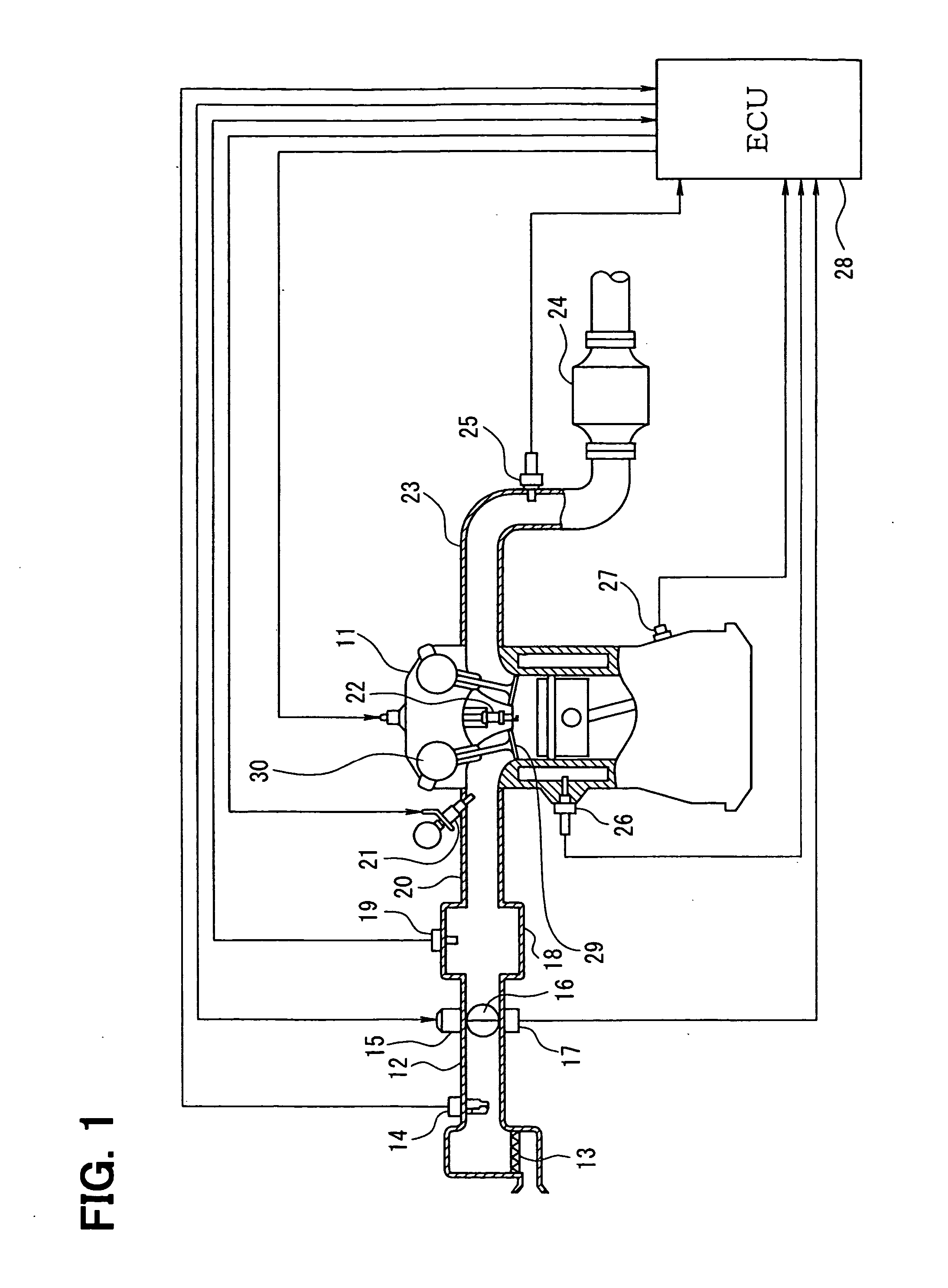
[0030] First, description will be given to the general configuration of an engine control system with reference to FIG. 1. An air cleaner 13 is provided at the most upstream portion of the intake pipe 12 of an internal combustion engine 11. An air flow meter 14 that detects the quantity of intake air is provided downstream of this air cleaner 13. Downstream of this air flow meter 14, there are provided a throttle valve 16 and a throttle angle sensor 17. The angle of the throttle valve 16 is adjusted by a motor 15 (e.g., a DC motor), and the throttle angle sensor 17 detects the angle of the throttle valve 16.

[0031] A surge tank 18 is provided downstream of the throttle valve 16, and this surge tank 18 is provided with an intake manifold pressure sensor 19 that detects intake manifold pressure. The surge tank 18 is provided with an intake manifold 20 that guides air into each...

second embodiment

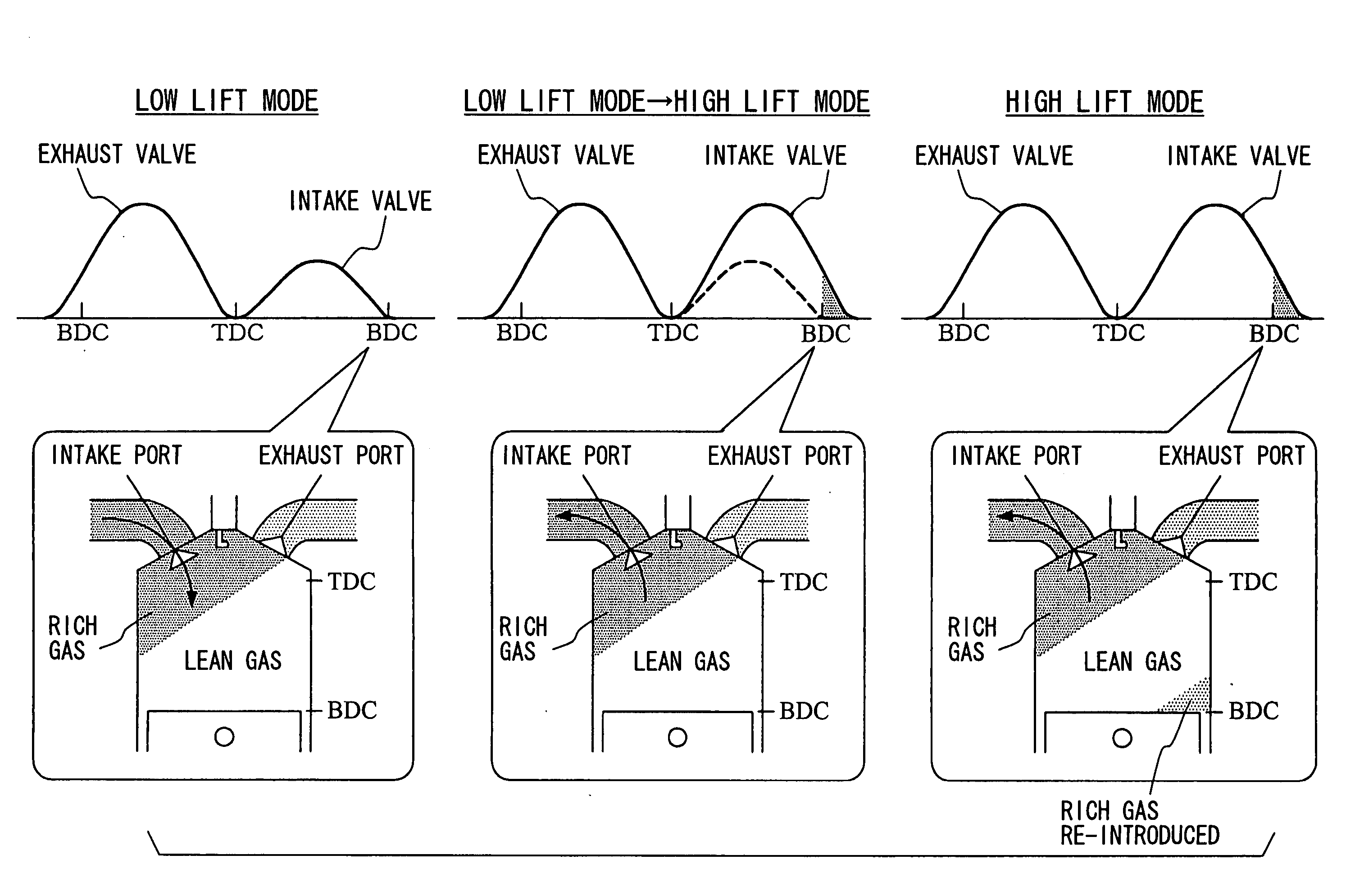
[0050] Next, description will be given to the second embodiment of the invention with reference to FIG. 5. Generally, when the variable intake valve lifter 30 is switched from low lift mode to high lift mode to increase the amount of lift of the intake valve 29, the injection quantity is corrected and increased to reduce the likelihood of a lean spike. Also, when the variable intake valve lifter 30 is switched from high lift mode to low lift mode to reduce the amount of lift of the intake valve 29, the injection quantity is corrected and reduced to reduce the likelihood of a rich spike.

[0051] The injection quantity computation program illustrated in FIG. 5 is executed at predetermined intervals while the engine is in operation. When the program is started, the current amount of lift of the intake valve is computed in Step S201, and the current valve closing timing of the intake valve is computed in step S202. Then in Step S203, the ECU computes a basic injection quantity based on t...

third embodiment

[0063] Description will be given to the third embodiment of the invention with reference to FIG. 6 and FIG. 7.

[0064] As illustrated in FIG. 6, the engine 11 is a four-valve engine having four valves for each cylinder. Each cylinder is provided with two intake ports 31 and two exhaust ports 32. Each intake port 31 is provided with an intake valve 29, and each exhaust port 32 is provided with an exhaust valve 33.

[0065] A swirl valve 34 (i.e., a swirl flow generating device) is included in either of the two intake ports 31 of the cylinder. The swirl valve 34 generates a swirl flow in the corresponding cylinder. The swirl valve 34 of each cylinder is so constructed that it is driven and opened / closed by a motor or the like (not shown). The ECU 28 executes the swirl valve control program illustrated in FIG. 7. As such, when the engine is in a predetermined operating range (e.g. low-revolution, low-load operating range, etc.), the swirl valve 34 is closed to generate a swirl flow in the...


PUM


Abstract

A control apparatus for an internal combustion engine that varies the amount of lift of an intake valve is disclosed. In one embodiment, the control apparatus includes a fuel injection timing correcting device that, when lift of the intake valve is varied, corrects and varies fuel injection termination timing according to the variation of the lift of the intake valve. In another embodiment, an injection quantity correcting device is included that, when lift of the intake valve is varied, corrects and varies an injection quantity. In still another embodiment, a swirl flow generating device is included that generates a swirl flow in the cylinder. In a further embodiment, an intake valve closing timing correcting device is included that, when lift of the intake valve is varied, controls the variable valve timing mechanism so that the valve closing timing of the intake valve remains substantially constant.

Description

CROSS REFERENCE TO RELATED APPLICATION [0001] The following is based on and claims priority to Japanese Patent Application No. 2005-264566, filed Sep. 13, 2005, which is incorporated herein by reference. FIELD [0002] The present invention relates to a control apparatus for an internal combustion engine that varies the amount of lift of an intake valve. BACKGROUND [0003] Internal combustion engines have been proposed that include a variable intake valve lifter that varies the amount of lift of an intake valve. An example of this type of variable intake valve lifter is disclosed in Japanese Patent No. 2827768. Specifically, the control mode of the variable intake valve lifter is switched between low lift mode and high lift mode in accordance with the state of operation of the internal combustion engine. In low lift mode, a cam for driving and opening / closing an intake valve is changed to a cam for low lift to reduce the amount of lift of the intake valve. In high lift mode, the cam fo...

Claims


Application Information

Patent Timeline
Patent Type & Authority Applications(United States)
IPC IPC(8): F01L1/34F01L9/04
CPCF01L1/053F01L13/0015F02D41/0002F02D41/40Y02T10/18F02D2041/0015Y02T10/146Y02T10/44Y02T10/42F02D2041/001Y02T10/12Y02T10/40
Inventor MORIMASA, TAKANOBU
Owner DENSO CORP
Why Eureka
Try Eureka