

Brake control apparatus and method for vehicle
a technology for controlling apparatus and brakes, applied in the direction of braking systems, braking components, transportation and packaging, etc., can solve the problems of abnormal noise, actuators producing self-excited vibrations, etc., and achieve the effect of suppressing the occurrence of self-excited vibrations
- Summary
- Abstract
- Description
- Claims
- Application Information
AI Technical Summary
Benefits of technology
Problems solved by technology
Method used
Image

Examples
first embodiment
[0055]FIG. 5 is a schematic view illustrating an entire configuration of a brake control apparatus 200A for a vehicle according to the present invention. Brake control apparatus 200A for a vehicle has an electronic control unit (ECU) 100, and a hydraulic brake system, which is described later, on a vehicle 10. ECU 100 of the embodiment functions as a brake ECU that controls the hydraulic brake system. The vehicle 10 of the embodiment equipped with an automatic transmission (not shown).
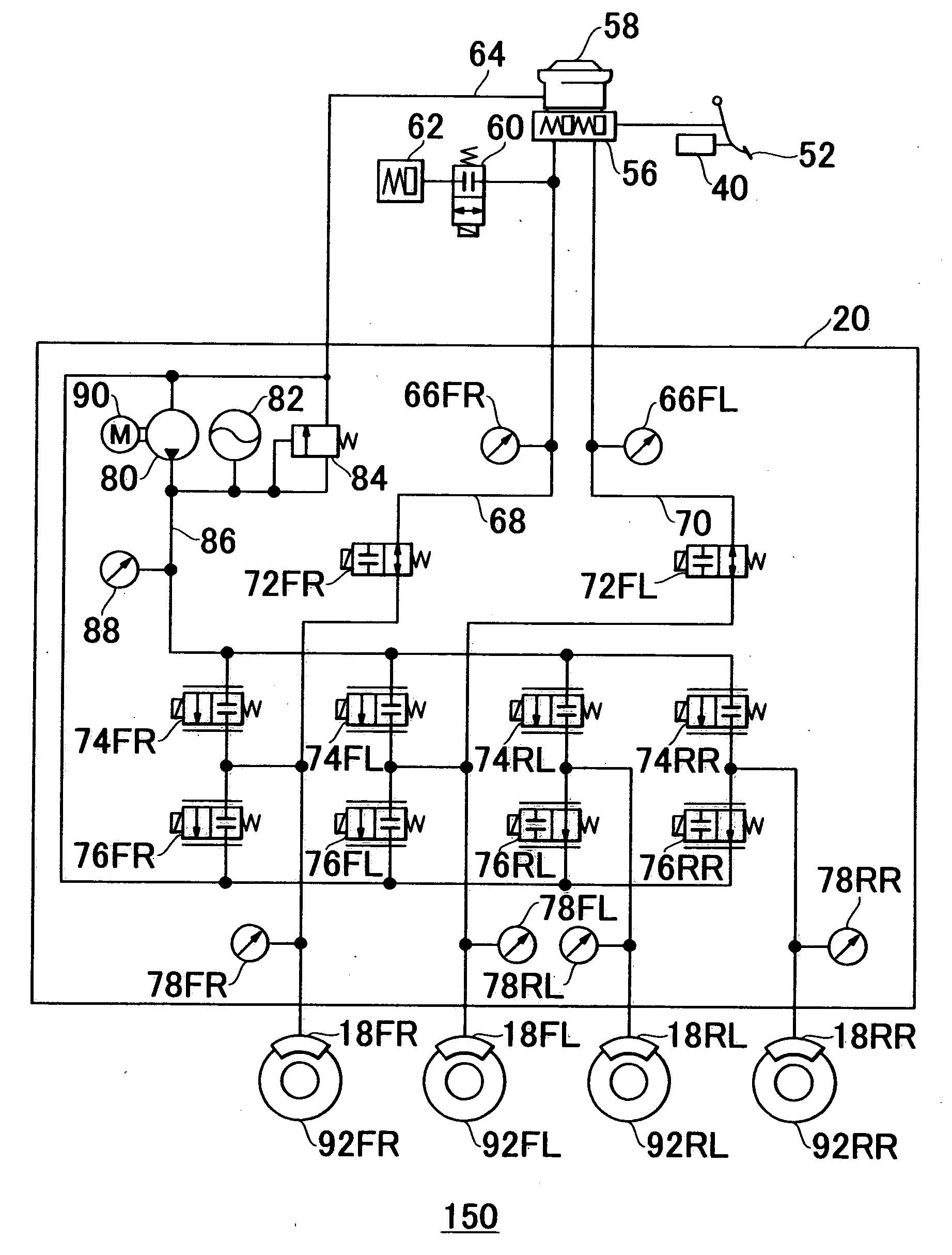
[0056] The hydraulic brake system includes front right wheel brake 92FR, front left wheel brake 92FL, rear right wheel brake 92RR and rear left wheel brake 92RL (hereinafter, collectively referred to as brakes 92). The hydraulic brake system further includes brake hydraulic pressure generator 20, a brake pedal 52, stroke sensor 40, or the like.
[0057] Front right wheel brake 92FR, front left wheel brake 92FL, rear right wheel brake 92RR and rear left wheel brake 92RL are provided in association with fr...
second embodiment
[0100]FIG. 11 is a view illustrating an example of a relationship between the temperature T of the hydraulic fluid in the pressure-reducing linear valves and the pressure reduction rate for reducing the wheel cylinder pressures, when the pressure reduction rate of the wheel cylinder pressure is limited to the ceiling value, in the brake control apparatus 200A for the vehicle according to the present invention.
[0101] As shown in FIG. 11, when the vehicle is in the low temperature, in which the coolant temperature is below the second temperature T2, the ceiling value Smax of the pressure reduction rate is gradually increased as the temperature decreases from the second temperature T2.
[0102] Accordingly, in addition to the range A0, the pressure reduction rate for reducing the wheel cylinder pressures can be changed in the range A2. Therefore, the ceiling value Smax of the pressure reduction rate can be increased within the range A2, compared with when the ceiling value Smax of the pr...
third embodiment
[0103]FIG. 12 is a schematic view illustrating an entire configuration of a brake control apparatus 200B for a vehicle according to the present invention. The brake control apparatus 200B includes ECU 100, engine ECU 160, engine 168, hydraulic brake system 150, which is similar to that explained in the previous embodiments, or the like, on vehicle 10. Hydraulic brake system 150 includes brake hydraulic pressure generator 20. ECU 100 of this embodiment functions as a brake ECU that controls the hydraulic brake system. In this embodiment, the vehicle 10 is equipped with an automatic transmission (not shown). The explanation of parts similar to those of the previous embodiments will be omitted.
[0104] The engine 168 includes intake path 166. The intake path 166 includes throttle valve 164 in the interior of the intake path 166. The throttle valve 164 is connected with throttle motor 162, and is driven by throttle motor 162. The throttle motor 162 is connected with engine ECU 160. The en...
PUM
 Abstract
Description
Claims
Application Information