Oblique mirror-type normal-incidence collector system for light sources, particularly euv plasma discharge sources

a collector system and mirror-type technology, applied in the field of mirror-type normal-incidence collector system, can solve the problems of grazing-incidence collectors' shadowing effects, inability to reduce the size of the illumination system, so as to achieve small radiation loss, large numerical aperture, and high collection aperture

Inactive Publication Date: 2007-03-15
CARL ZEISS SMT GMBH
View PDF18 Cites 25 Cited by
  • Summary
  • Abstract
  • Description
  • Claims
  • Application Information

AI Technical Summary

Benefits of technology

[0012] The object of the invention consists of configuring a collector system consisting of normal-incidence mirrors for a light source, in particular, an EUV light source, whereby laser plasma or discharge light sources are particularly preferred for this source, in such a way that the problems of the prior art indicated above are overcome. Thus, a particularly well-cooled collector system should be provided which takes up the radiation of the light source with a large numerical aperture and thus a high collection aperture, as well as simultaneously makes possible small radiation losses as well as angles of incidence that are as small as possible on the multi-layer reflection films of the mirrors of the collector. The collector system will also provide sufficient structural space for the screening of the light source and contribute to an overall length of the illumination system that is as short as possible, as well as produce a spectrally pure illumination radiation.
[0013] The inventors have recognized that with a collector system comprised of two normal-incidence mirrors, when employing an oblique mirror-type structure of a Schwarzschild system, a high collection aperture can be combined with sufficiently small angles of incidence. Collection aperture is understood in the present Application as the numerical aperture taken up by the first collector mirror; this is designated below as the first numerical aperture, to which is assigned a first aperture angle. For this purpose, a collector system according to the invention is constructed in such a way that the numerical aperture bent back, i.e., reflected, from a first normal-incidence mirror is smaller than or equal to the collection aperture. Resulting from this is an increase of the mirror size of the second normal-incidence mirror, which in turn is positioned at a distance to the first normal-incidence mirror, which approximates as much as possible the distance to the source. According to the invention, this is achieved by a non-symmetrical structure, i.e., an oblique mirror-type construction of the collector. It is to be understood by this that the axial symmetry of the collector is no longer given. Here, the second normal-incidence mirror is essentially positioned next to the light source. Sufficient structural space for the inclusion of the light source in its own compartment can be created thereby and at the same time, the second normal-incidence mirror can be formed correspondingly enlarged and can be positioned at a sufficient distance to the first normal-incidence mirror. Also, with such an arrangement, the back side of the mirror elements can be cooled in a simple manner.

Problems solved by technology

In this case it also must be taken into consideration that it is not possible using this principle to bend back the beam path in the vicinity of the light source which would reduce the size of the illumination system, and also the extension of the light source also runs counter to such bending back according to the current prior art.
Another disadvantage of grazing-incidence collectors is their shadowing effects, which arise due to the unavoidable mechanical holders, particularly in the case of a nested structure.
These collectors can be constructed in a filigree pattern, e.g., in the form of a spoked wheel, but these lead to radiation losses especially in the case of small sources.
A similar problem results with respect to the cooling equipment of the grazing-incidence collector, which adds further mechanical structures and thus contributes to the shading losses.
Such cooling equipment cannot be omitted, since for lithography at 13.5 nm, due to the necessity of forming a vacuum, the heat transfer is insufficient and the thermal stress would lead to an intolerable deformation of the mirror shells.
If a discharge source is present instead of a laser plasma source, then the space requirement which results due to the extended electrodes leads to an intense reduction of the illumination power.
Here, it is impossible, for reasons of space, to arrange a particle filter after the light source, so that there is a particularly rapid polluting of normal-incidence mirrors in the vicinity of the source.

Method used


Image

  • Oblique mirror-type normal-incidence collector system for light sources, particularly euv plasma discharge sources
  • Oblique mirror-type normal-incidence collector system for light sources, particularly euv plasma discharge sources
  • Oblique mirror-type normal-incidence collector system for light sources, particularly euv plasma discharge sources

Examples


Embodiment Construction

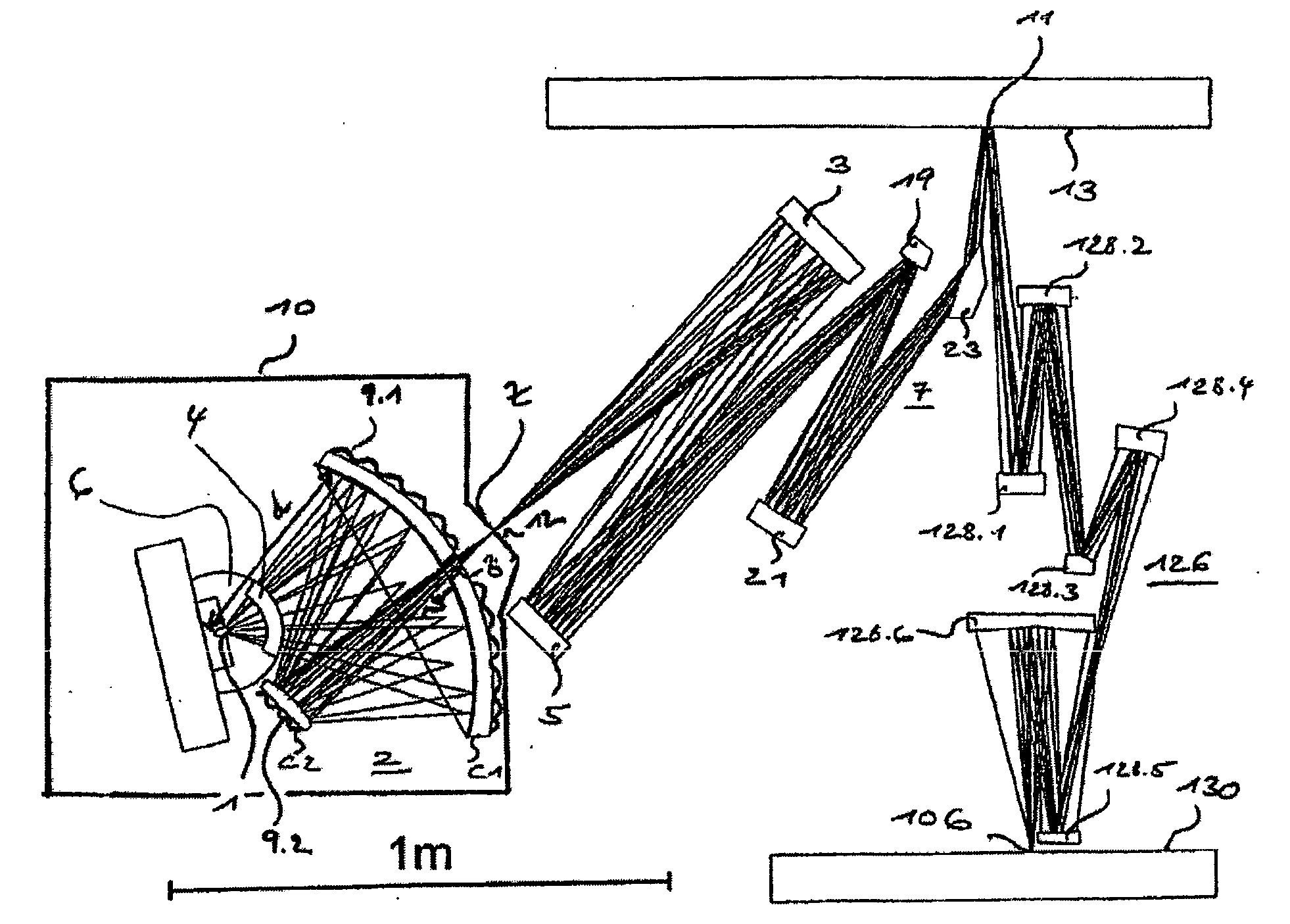
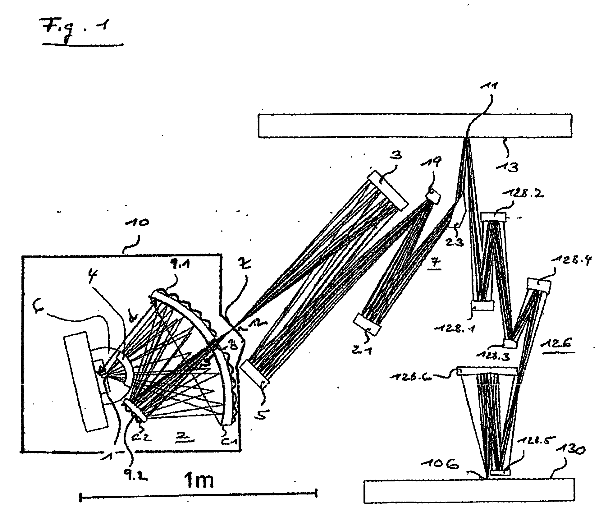
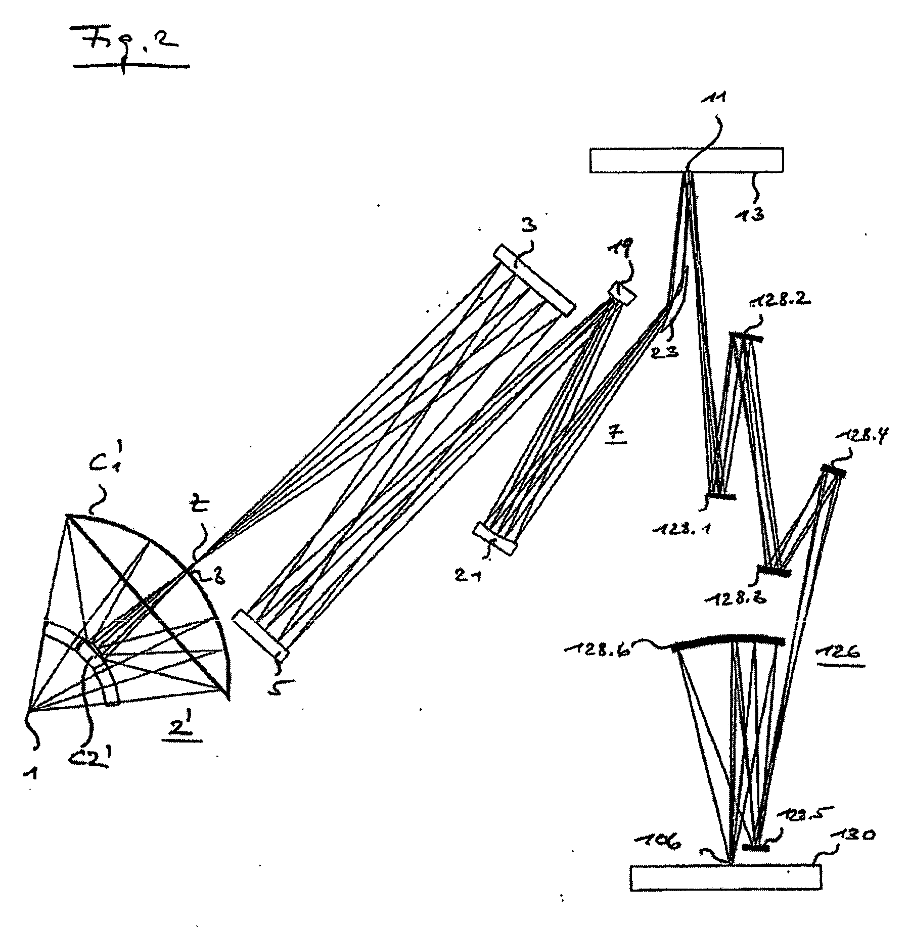
[0021]FIG. 2 shows the typical structure of an EUV lithography system for microlithography, which comprises a Schwarzschild collector system 2′ corresponding to the prior art.

[0022] The schematically simplified representation of the Schwarzschild collector system 2′ shows a first normal-incidence collector mirror C1′, which takes up light from light source 1 by its concave, for example, parabolic or elliptical shape and bends it back, i.e., reflects it, onto the second normal-incidence collector mirror C2′, which in turn can be of hyperbolic or ellipsoid shape. This second normal-incidence collector mirror C2′ is thus disposed so that it is centered relative to the first normal-incidence collector mirror C1′, so that a symmetrical collector system is formed, which images the light source 1 onto a magnified intermediate image Z. A passage 8 is provided in the first normal-incidence collector mirror C1′ for the radiation exiting from the second normal-incidence collector mirror C2′. ...


PUM

PropertyMeasurementUnit
distanceaaaaaaaaaa
wavelengthsaaaaaaaaaa
widthaaaaaaaaaa

Abstract

There is provided a collector system. The collector system includes a first collector mirror and a second collector mirror. The first collector mirror receives EUV light from a light source at a first aperture angle via a first beam path, and reflects the EUV light at a second aperture angle along a second beam path. The first aperture angle is larger than or substantially equal to the second aperture angle. The second mirror receives the EUV light from the first mirror at the second aperture angle. The collector is an oblique mirror type normal incidence mirror collector system.

Description

BACKGROUND OF THE INVENTION [0001] 1. Field of the invention [0002] The invention relates to an oblique mirror-type normal-incidence collector system, in particular for light sources which predominantly emit radiation with wavelengths of ≦193 nm. Most particularly preferred are EUV light sources, in particular EUV plasma discharge sources. In addition, the invention describes an illumination system comprising such a collector system, which preferably is assigned to an EUV projection exposure unit, in particular for EUV lithography. [0003] 2. Description of the Prior Art [0004] In order to be able to still further reduce pattern widths for electronic components, in particular to the submicron range, it is necessary to reduce the wavelengths of the light used for microlithography. The use of light with wavelengths of ≦193 nm is conceivable, for example, lithography with soft x-rays, so-called EUV lithography. [0005] EUV lithography is one of the most promising lithography techniques f...

Claims


Application Information

Patent Timeline
Patent Type & Authority Applications(United States)
IPC IPC(8): G06K7/10G03F7/20G11C11/22
CPCG03F7/70175G03F7/70075G03F7/70116
Inventor SINGER, WOLFGANG
Owner CARL ZEISS SMT GMBH
Why Eureka
Try Eureka