Distributed quality-of-service management system

a management system and quality management technology, applied in the field of distributed quality-of-service management system, can solve the problems of becoming more difficult in a distributed system, and achieve the effect of maximizing the available resources and the available bandwidth of the wireless connection, increasing the overall performance of the system, and sufficient bandwidth

Inactive Publication Date: 2007-03-15
FG MICROTEC
View PDF1 Cites 58 Cited by
  • Summary
  • Abstract
  • Description
  • Claims
  • Application Information

AI Technical Summary

Benefits of technology

[0021] In prior art solutions, the application unit has not been aware of the flow parameters on the modem unit, and the modem unit has not been aware of the applications and the flow parameters on the application unit. The embodiments of the present invention allow for an exchange of flow control information between the application unit and the modem unit. On both of the units, said flow control information is helpful for utilizing the available resources and the available bandwidth of the wireless connection as efficiently as possible. Each of the units is informed about the overall system state and may react accordingly. As a result, the system's overall performance is increased. A smooth adaptation of the system's control settings is achieved, and the applications' QoS requirements can be fulfilled to a degree that has not been possible yet.
[0022] According to a preferred embodiment of the invention, said at least one physical interface is realized as or comprises at least one serial interface, in particular at least one of a RS232, IrDA, Bluetooth, USB, PCMCIA, UART interface. A serial interface provides sufficient bandwidth for transmitting both application-related data traffic and flow control information between the modem unit and the application unit.

Problems solved by technology

Whereas in an embedded system it is relatively easy to realize this vertical connection between the different layers, it becomes more difficult in a distributed system.

Method used


Image

  • Distributed quality-of-service management system
  • Distributed quality-of-service management system
  • Distributed quality-of-service management system

Examples


case 2

Transport in Idle Mode

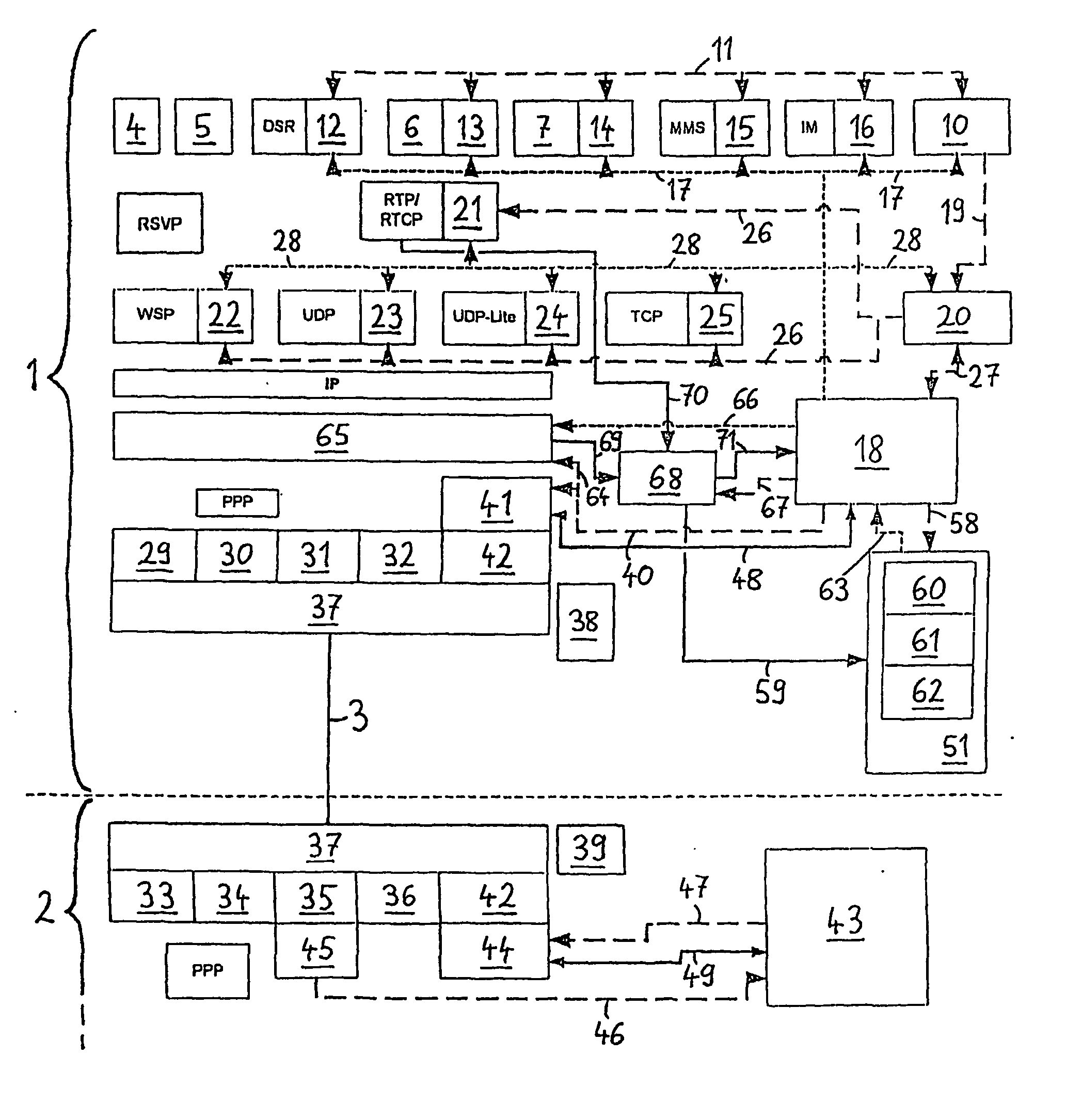
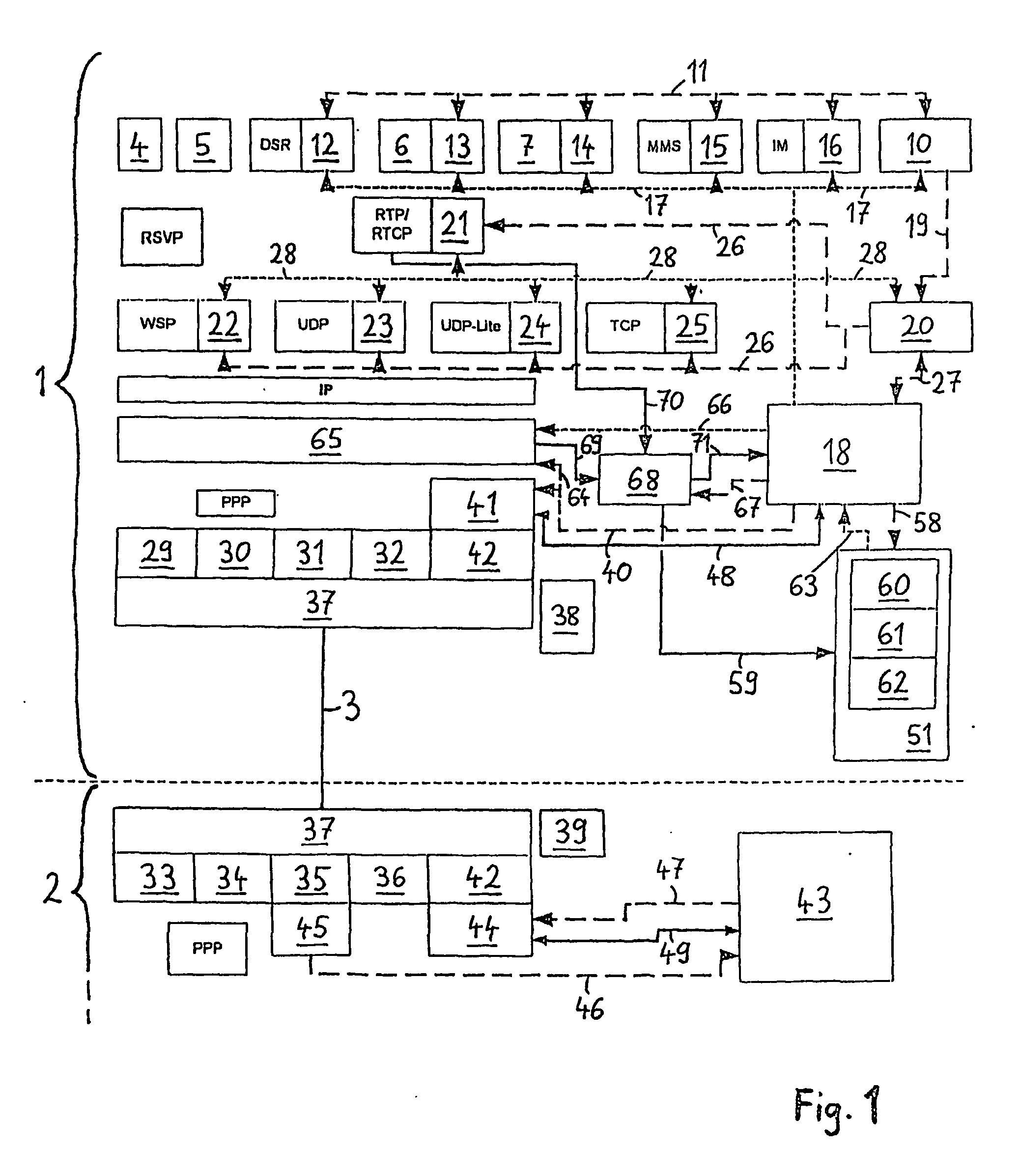
[0136] In an idle mode no IP address is assigned to the IP stack in the application unit for this modem connection. No PPP connection is active. If the AU collector wants to get measurements from the modem in idle mode it builds up a PPP connection to the modem using a very special string as dial up number (e.g. **3*4*6**# or **f*g*m**#), which is recognized from the sender in the modem as its own number. The IP address for this connection is assigned in the following way: The AU collector uses in the PAP (Password Authentication Protocol, part of the PPP initiation) as username a desired IP address for itself (it can be that other IP addresses are defined in the Application unit already and the IP address of this connection must be unique). The modem assigns this IP address in the IPCP (IP Control Protocol) negotiation (which is part of the PPP negotiation) to the IP stack of the application unit for this modem connection. Again, the sender uses the next highe...


PUM


Abstract

An application unit and a modem unit for mobile communication are provided. The application unit comprises at least one application that exchanges data traffic with at least one protocol stack, wherein said at least one protocol stack transfers data between at least one of the applications and at least one physical interface. The modem unit comprises a broadcast facility for setting up a wireless connection, and at least one transmission protocol stack for transferring data traffic between the at least one physical interface and the broadcast facility. The modem unit collects flow control information about the status of the wireless connection. The flow control information are packed into an IP packet which is sent via the physical interface to the application unit. The application unit uses the received flow control information to optimize the quality of service.

Description

BACKGROUND OF THE INVENTION [0001] Mobile devices might comprise applications, protocol stacks as well as a modem unit adapted for establishing a wireless connection with a mobile communication network, whereby all said entities may run on one processing system. The modem unit might as well be installed on a different processing resource than the applications. Besides that, for the modem unit, a first operating system might be used, and for the applications, another operating system might be employed. It is expected that in the future, more and more user terminals will be available that do not comprise a proprietary modem unit. Instead, said user terminals will comprise a physical interface for establishing a connection between said user terminal and an external modem unit, whereby the external modem unit will be responsible for setting up a wireless connection with the mobile communication network. Besides that, phones will be available where an additional processing resource and / o...

Claims


Application Information

Patent Timeline
Patent Type & Authority Applications(United States)
IPC IPC(8): H04J3/16H04L12/28H04L47/2416H04L47/30H04L47/80
CPCH04L29/06H04L69/32H04L47/11H04L47/125H04L47/14H04L47/19H04L47/2416H04L47/30H04L47/801H04L47/803H04L47/823H04L47/824H04W28/10H04L69/24H04L47/10H04W28/02H04L9/40H04L47/83H04W8/04
Inventor HOFFMANN, MATTHIASKETZ, THOMASMIRBAHA, VAHID ROBERT
Owner FG MICROTEC
Why Eureka
Try Eureka