Fiber bragg grating sensor system

a sensor system and fiber bragg technology, applied in the field of fiber bragg grating sensor system, can solve the problems of deteriorating accuracy and repeatability in long-term measurement, measurement error, and inability to linearly vary the wavelength of the practically used tunable filter according to the applied

Active Publication Date: 2007-03-15
FIBERPRO INC
View PDF9 Cites 38 Cited by
  • Summary
  • Abstract
  • Description
  • Claims
  • Application Information

AI Technical Summary

Problems solved by technology

However, in the above-described methods, the wavelength of the practically used tunable filter is not varied linearly according to the applied voltage.
Also, there is a problem of deteriorating accuracy and repeatability in long-term measurement due to the wavelength drift of the filter caused by hysteresis or temperature change.
Moreover, in those methods an error caused by polarization dependency and the solutions thereof are not disclosed.
However, if the wavelength of the reference fiber grating 15 varies in temperature, etc., the described method is to have an error in measuring the wavelength.
However, this method has a drawback of requiring an additional light source, i.e. a second light source 4.
Accordingly, in this method, there is a drawback of a limitation in speed for obtaining wavelength information of the input light signal due to generation of the wavelength reference employing the time-division method.
However, polarization dependency, one of the essential factors causing accuracy problems in measuring, can be present in the fiber Bragg grating, the Fabry-Perot filter, the photodetector, and so on.
Particularly the polarization dependency of the fiber grating in itself can generate significant errors in measuring a change in strain.
As a result, the wavelength is changed according to the polarization states, thereby errors occurring in measuring.
However, these methods are expensive and non-effective.
By the way, if the input polarization states are varied or a detection system for light signals has the polarization dependency, stable signals cannot be obtained in measuring.
Accordingly, the fast polarization scrambler, which may be very expensive and increase insertion loss, is required for fast measurement of strain.

Method used


Image

  • Fiber bragg grating sensor system
  • Fiber bragg grating sensor system
  • Fiber bragg grating sensor system

Examples


Embodiment Construction

Technical Subject

[0030] The object of the present invention provides a fiber Bragg grating sensor system not only for measuring and calibrating wavelength of a wavelength tunable laser used as a light source but also for actively controlling the wavelength of the light source with the calibration result.

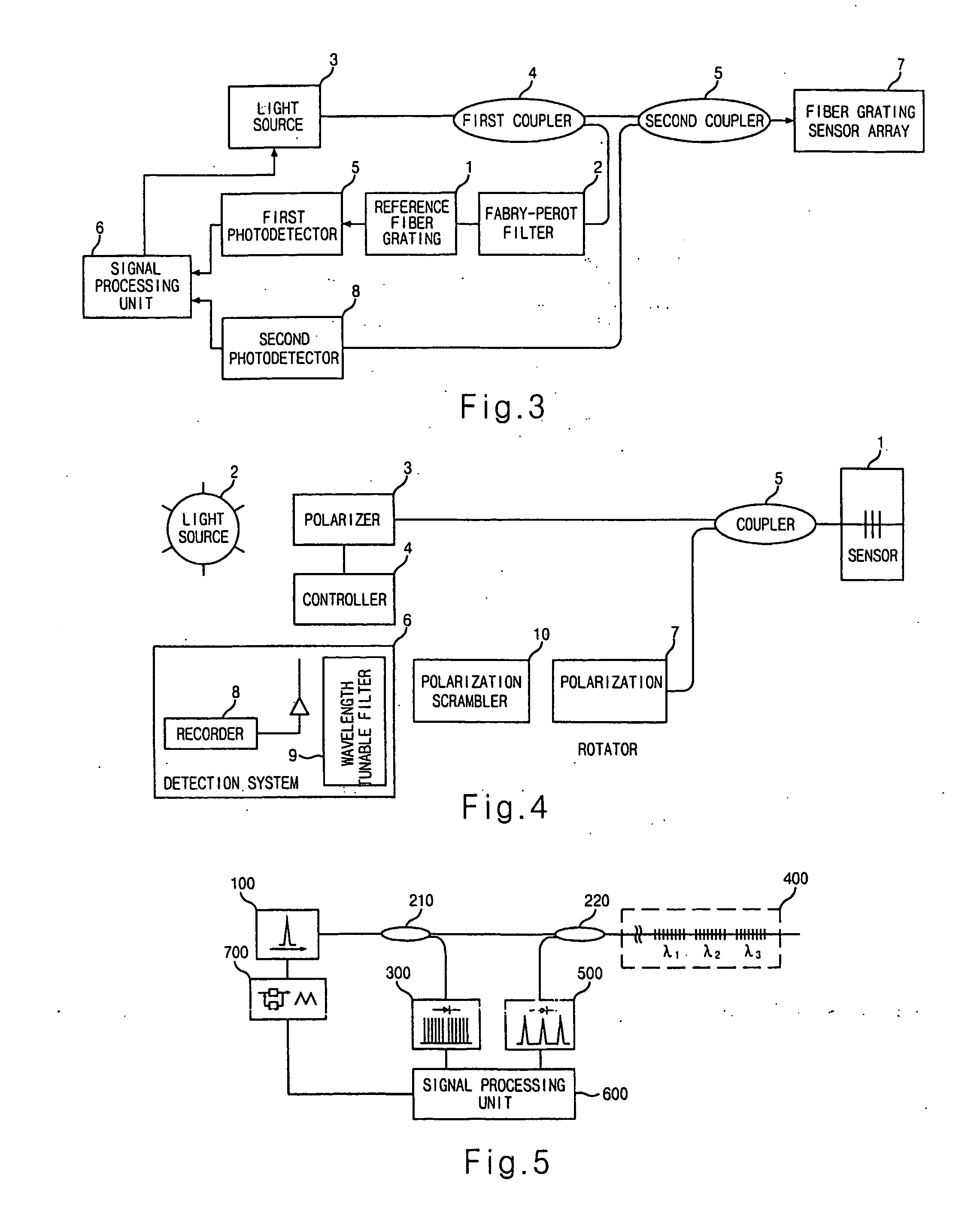
[0031] Another object of the present invention provides a fiber Bragg grating sensor system for simultaneously solving polarization dependency caused in measuring a change in strain.

Technical Solution

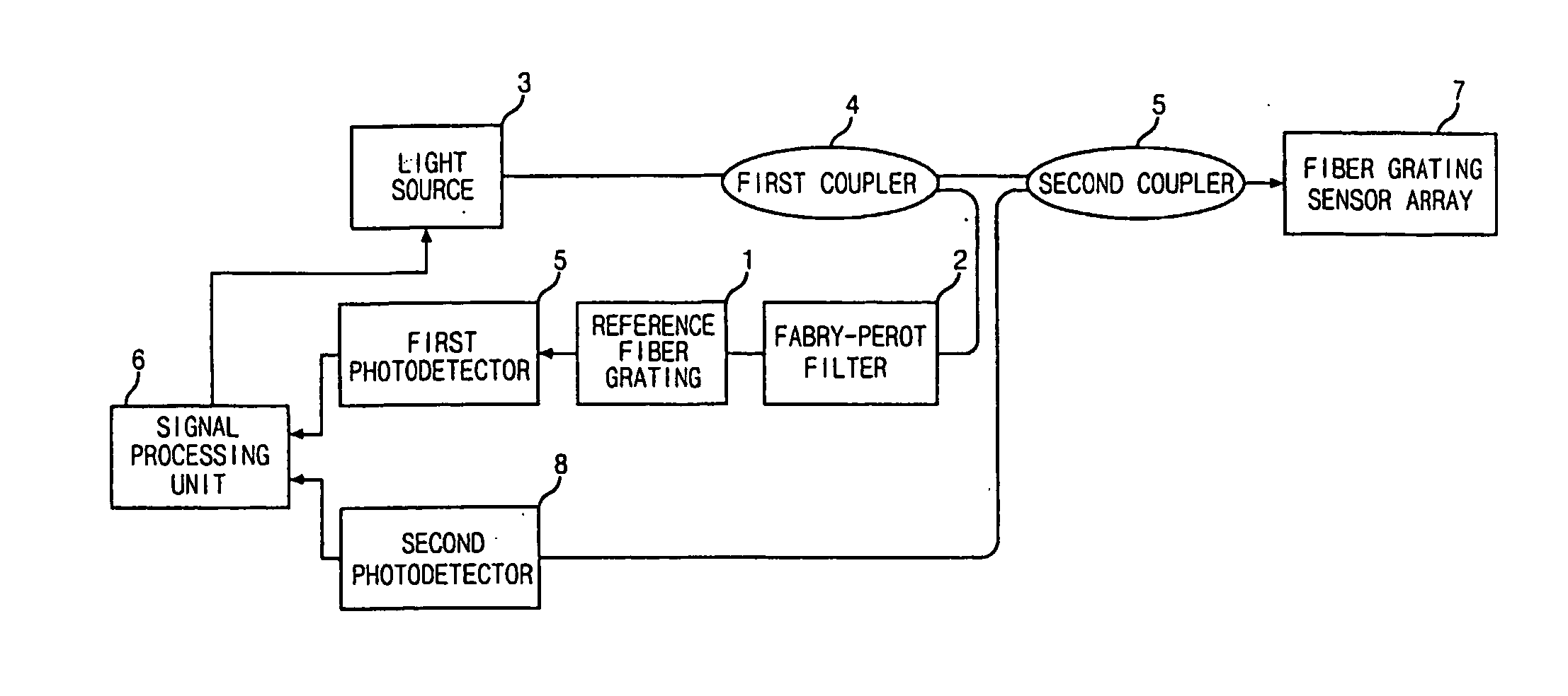
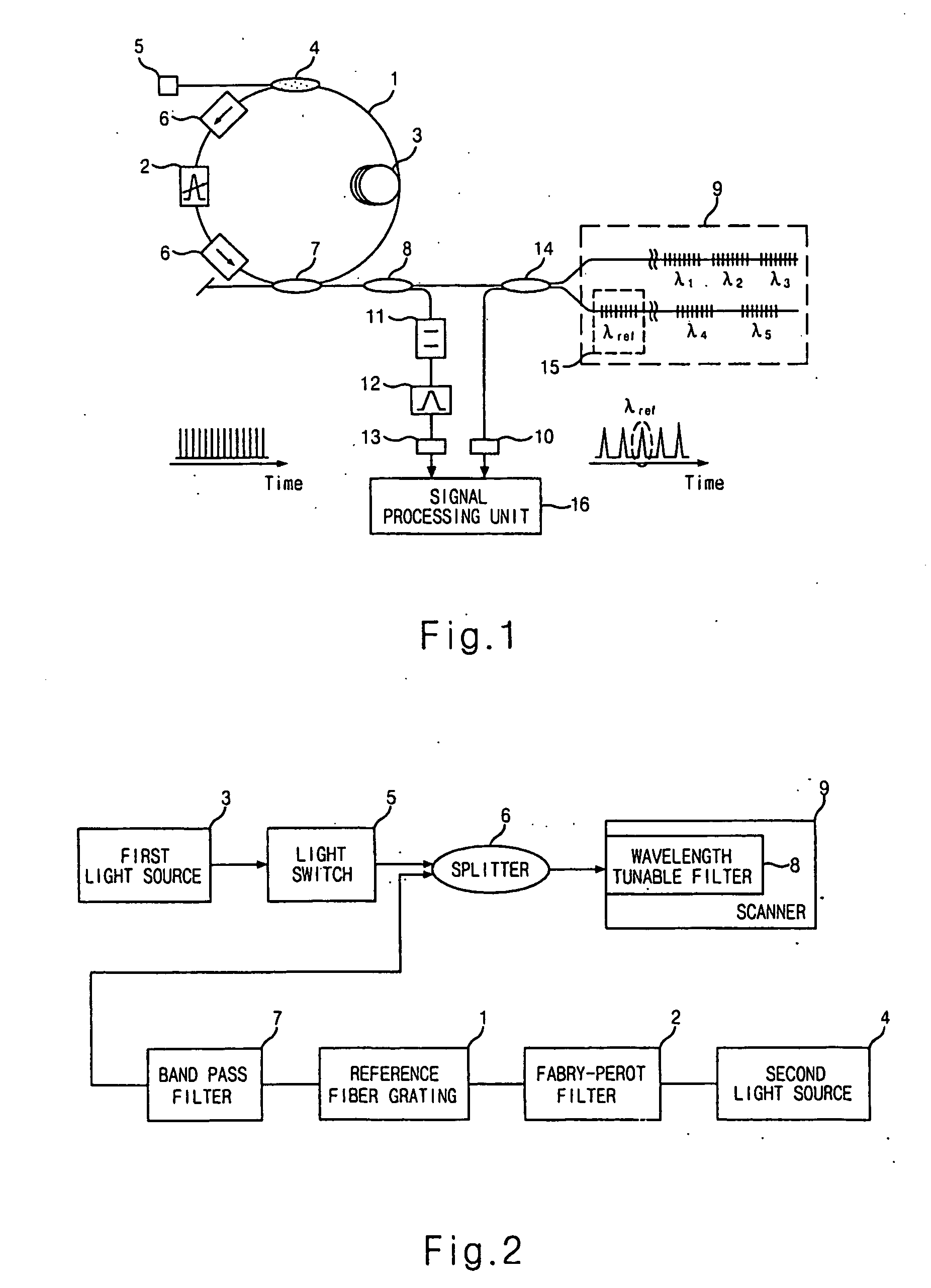
[0032] In order to achieve the above-described objects, a fiber Bragg grating sensor system according to the present invention comprises a wavelength tunable laser including a wavelength tunable laser including a wavelength tunable filter for outputting a tunable wavelength light, a first coupler for receiving the light outputted from the wavelength tunable laser and for splitting the light into two directions, a reference wavelength generating unit for receiving one of lights spli...


PUM


Abstract

The present invention discloses a fiber Bragg grating sensor system. The system according to the present invention comprises a wavelength tunable laser; a coupler for splitting output light from the wavelength tunable laser into two directions; a reference wavelength generating unit for receiving one directional output light from the coupler and for generating reference wave-lengths and an absolute reference wavelength in order to measure real-time wavelengths of the wavelength tunable laser; a fiber Bragg grating array for receiving the other directional output light from the coupler and for reflecting lights at each of the wave-lengths of the grating therein; a fiber grating wavelength sensing unit for measuring the time when each of the reflected lights from the fiber Bragg grating array is detected; a signal processing unit for figuring wavelength variation information with the use of the measured signals from the reference wavelength generating unit and for obtaining each of wavelengths of the detected lights from the fiber grating wavelength sensing unit; and a laser wavelength control feedback unit for applying AC voltage and DC voltage to the wavelength tunable filter in the wavelength tunable laser. Also, polarization dependency in the sensor system can be removed further installing a depolarizer or a polarization scrambler at the output end of the wavelength tunable laser. By applying the present invention, measurement accuracy of the grating sensor system 20 can be improved due to enhanced wavelength stability and suppression of polarization dependency. Therefore, the fiber Bragg grating sensor system based on the present invention would replace conventional structure/construction diagnosis systems.

Description

TECHNICAL FIELD [0001] The present invention generally relates to a fiber Bragg grating sensor system. Particularly, it relates to a fiber Bragg grating sensor system, which improves wavelength stability and repeatability of a wavelength tunable laser, and increases system accuracy by removing polarization dependency. BACKGROUND ART [0002] A fiber Bragg grating is to induce a periodical modulation of the refractive index in the core of an optical fiber. The fiber grating is characterized in that it reflects only light within a narrow bandwidth (generally, 0.1˜1nm) centered at Bragg wavelength, which meets the Bragg conditions and otherwise transmits. The Bragg wavelength is varied according to a change in temperature of the fiber Bragg grating and stress applied thereto. Thus, many fiber grating sensors have been developed using the above characteristics in order to measure any perturbations in temperature, strain, or stress. [0003] An advantage of these fiber grating sensors is to ...

Claims


Application Information

Patent Timeline
Patent Type & Authority Applications(United States)
IPC IPC(8): G02B6/00G01D5/353
CPCG01D5/35303G01D5/35316G01D5/35354G01D5/353
Inventor YONG, JAE CHULKIM, JAE YOUNG
Owner FIBERPRO INC
Why Eureka
Try Eureka