
Tuneable grating assisted directional optical coupler

a directional optical coupler and assisted grating technology, applied in the direction of optics, optical waveguide light guides, instruments, etc., can solve the problems of affecting the long-term affecting the reliability of the coupler, and the high cost of the circulator, so as to achieve good thermo-optical properties

Inactive Publication Date: 2007-03-15
GOOGLE LLC
View PDF5 Cites 12 Cited by
  • Summary
  • Abstract
  • Description
  • Claims
  • Application Information

AI Technical Summary

Benefits of technology

[0023] Temperature variations not larger than 100° C. are preferred to improve the stability of the employed polymers. More generally, temperature variations not larger than 100° C. are preferred because functioning of the optical device, i.e., the coupler, can be attained with relatively low power consumption.
[0026] Although electro-optic materials are possible tuneable materials according to the invention, in particular in a technology based on silicon-compounds materials, employment of polymers is preferred to that of liquid crystals because in the latter case technology can be more complex as confinement materials are necessary to confine the liquid crystal. Furthermore, the employment of electro-optic materials generally requires two electrodes for the tuning of the electric field of the tuneable material. This may increase complexity of the tuneable device when compared to the employment of thermo-optic materials.
[0029] As a preferred embodiment, a first silicon compounds-based waveguide comprising a first core and a first cladding is realised on a substrate and on top of the first silica-based waveguide a second silica-based core is fabricated. A tuneable polymer cladding is then deposited onto the second core. This allows to avoid any rather complex polymer etching or troubles of connections between polymer and silica. This embodiment of the invention allows therefore to combine the good thermo-optical properties of polymers and the quality of the silicon-compounds based waveguides without giving rise to complex fabrication steps.

Problems solved by technology

This may restrict the applications where the desiderable tuning range is of several nm.
Applicants have noticed that employment of polymeric materials with high dn / dT in the waveguide core region makes polymer stability a crucial issue and may affect long-term reliability of the coupler.
Furthermore, for an OADM (Optical Add / Drop Multiplexer) consisting of a waveguide and two optical circulators, the high cost of the circulators makes the device too expensive.
Applicants have noted that, in order to obtain a tuning of several nm, for example of 10-11 nm, the temperature of III-V semiconductors such as InGaAsP should be varied of at least 500° C., which implies a huge thermal variation of the overall device, which can be detrimental for the device performances.
They have further observed that fabrication technology based on III-V semiconductors is rather complex and expensive.
This device would be unsuitable for making a tuneable directional coupler.

Method used


Image

  • Tuneable grating assisted directional optical coupler
  • Tuneable grating assisted directional optical coupler
  • Tuneable grating assisted directional optical coupler

Examples


example 1

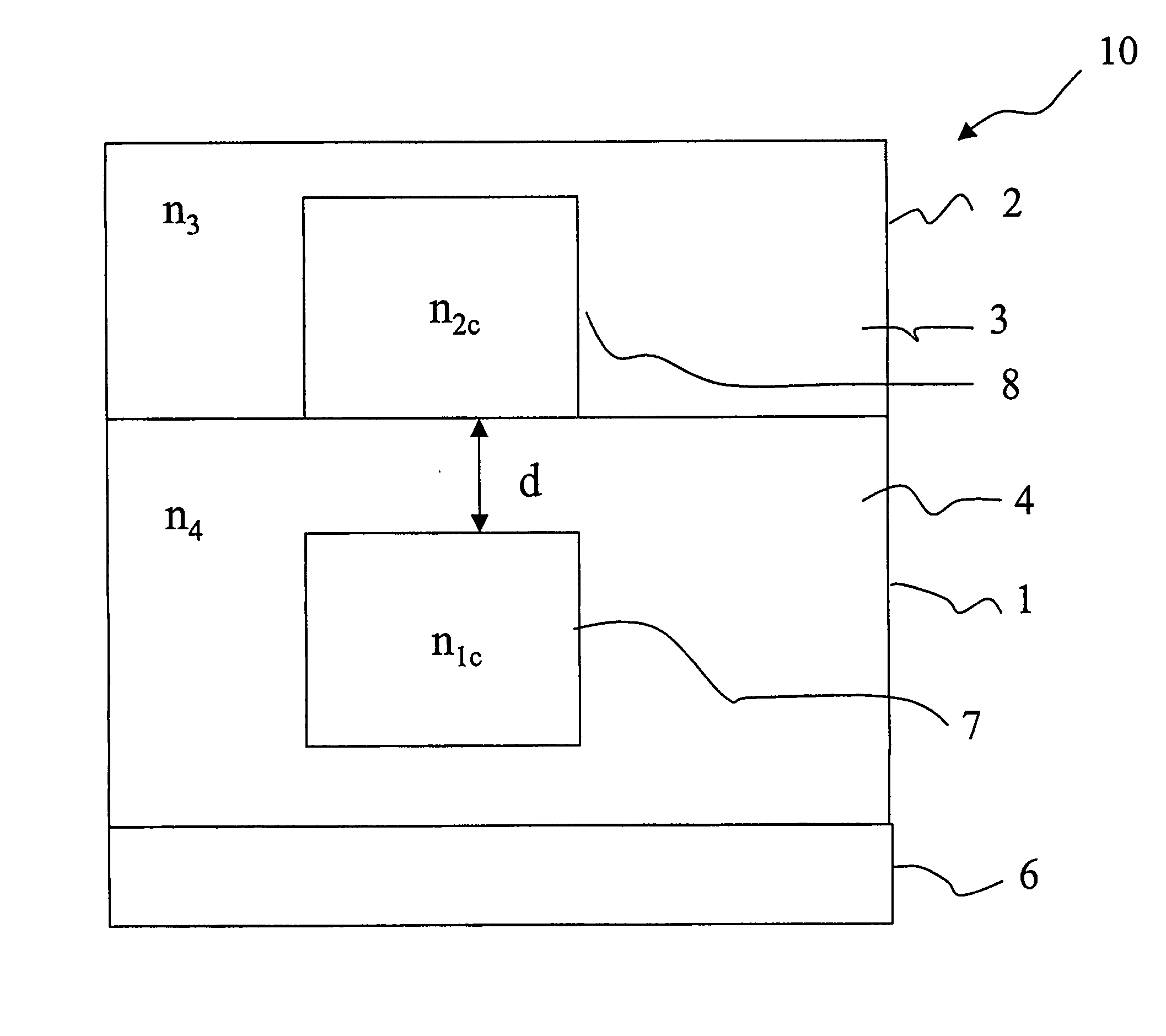
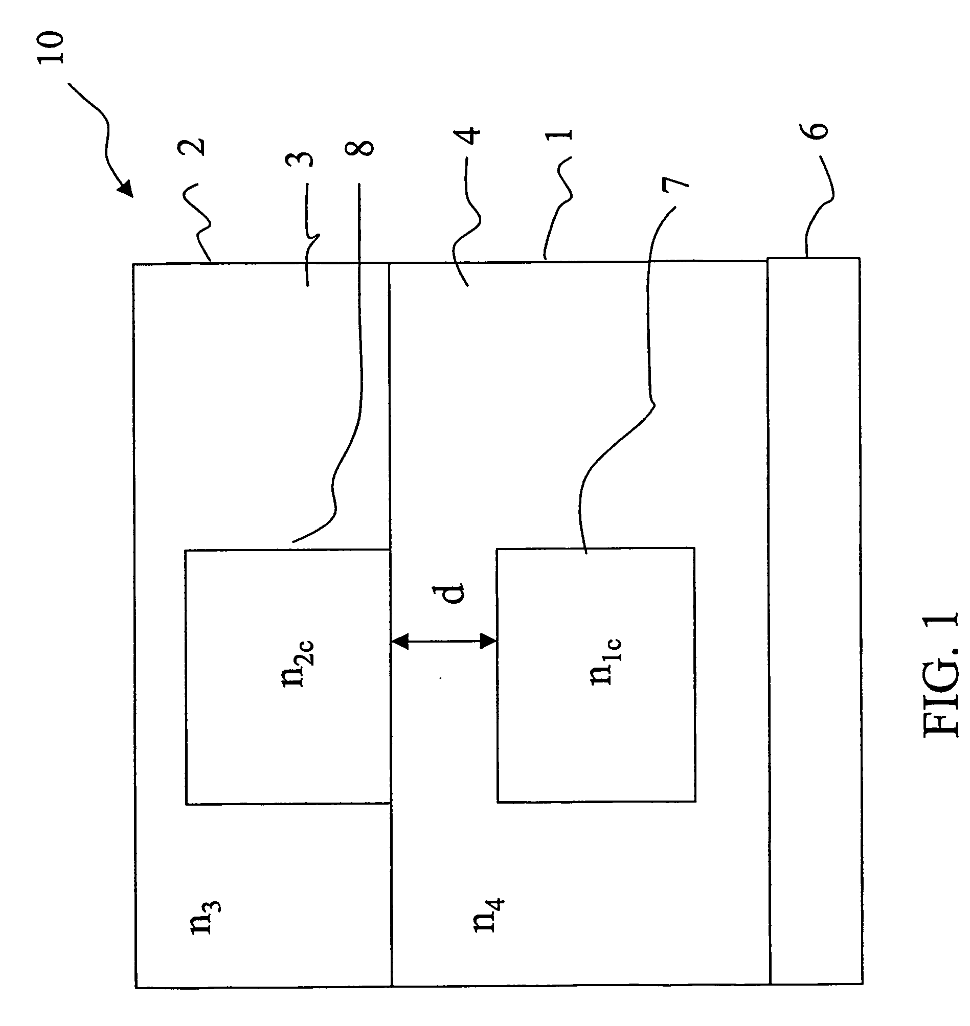
[0064] Referring again to FIG. 1, a contra-directional coupler 10 including two vertically stacked waveguides 1,2 on a substrate 6 is shown. The input waveguide in whose core also the grating is formed is the lower waveguide 1. The filtered wavelength is transferred to the upper waveguide 2. The core of the input waveguide 7 is square, its dimensions are 1.1×1.1 μm2 and it is realised in SiOx1Ny1 having a refractive index n1c of 1.7, while the core 8 of the output waveguide 2 is also square (1.1×1.1 μm2 as above) and it is realised in SiOx2Ny2 having a refractive index n2c of 1.567. The distance d between the two cores is 1.5 μm. The lower cladding material 4 is undoped silica, with a refractive index n4 of 1.446. The lower waveguide 1 and upper core 8 are fabricated following standard techniques. The last fabrication process is a deposition over the upper core 8 of the upper cladding 3, in particular by spin-coating, which is realized in DeSolite™ 3471-1-129 produced by DSM. This p...

example 2

[0065]FIG. 4 shows an alternative embodiment of a contra-directional coupler 10. The lower input waveguide 1 is realized as in example 1, while the upper waveguide 2 is an inverse ridge waveguide having the upper cladding 3 in a tuneable material, particularly in made of Sylgard™. In this example, the refractive index n3(T) of the upper cladding 3 goes from n3=1.4 to n3=1.37 for a temperature variation of 103° C. (the thermo-optic coefficient is equal to −2.9×10⁻⁴ / ° C.). Upper core 8, lower core 7 and lower cladding 4 are made of silicon-compounds materials. This structure may be advantageous because an accurate control of the thickness of the core—and thus of the coupler birefringence—can be achieved. Indeed, to control the coupler birefringence, it is necessary to control, among others, the dimensions of the core. In the coupler of example 1, this can be obtained varying the size of the core, in the specific case the length of the side of its square cross-section, during the etchi...

example 3

[0068]FIGS. 5 and 6 schematically illustrate a cross-sectional view and a lateral cross-sectional view, respectively, of a co-directional coupler comprising two vertically stacked waveguides 1,2. The input waveguide is the lower waveguide 1 which has a Ge-doped silica square (6×6 μm2) core 7 with refractive index n6 of 1.456 and a silica cladding 4 with refractive index n8 of 1.446 on a silicon wafer substrate 6. The square (6×6 μm2) core 8 of the output waveguide 2 is realized in silicon oxynitride (SiOxNy) and has a refractive index n5 of 1.49. The second tuneable cladding 3 is made of DeSolite™ 3471-1-129, whose refractive index n7(T) at room temperature is n7=1.48. A metallic electrode 15 is placed on the top of the upper waveguide to actuate the tuning.

[0069] The grating 12 is realized on the upper core 8 and has a period Λ=47,805 μm for a total length of about 5,76 cm (1205 periods). In particular, the grating is realized on the top portion of the core of the output waveguide...


PUM

PropertyMeasurementUnit
temperatureaaaaaaaaaa
electric fieldaaaaaaaaaa
wavelengthaaaaaaaaaa

Abstract

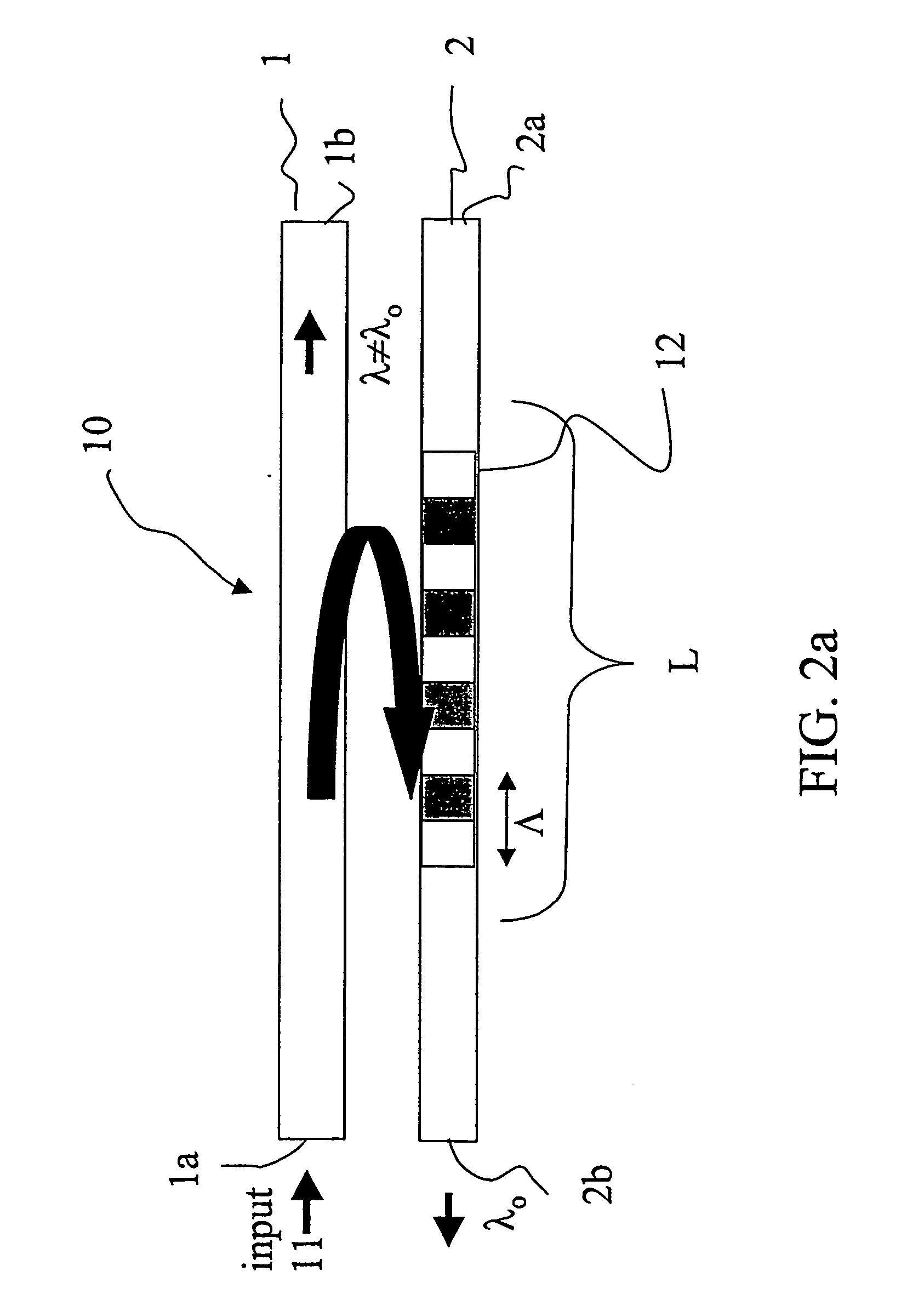
A tuneable grating assisted directional optical coupler to couple a transmission signal has a first waveguide including a first core and a first cladding, the first waveguide having a first effective refractive index. The coupler also has a second waveguide including a second core and a second cladding, the second waveguide having a second effective refractive index different from the first effective index and being in substantially close proximity to the first waveguide in a predetermined region to provide coupling therebetween. A periodic perturbation is positioned in the coupling region to cause the coupling to be wavelength selective for one given wavelength function of the first and / or the second effective refractive index. Additionally, the second cladding of the second waveguide has a tuneable material and the first cladding of the first waveguide has a non-tuneable material.

Description

TECHNICAL FIELD [0001] The invention relates to a tuneable grating assisted directional optical coupler, which couples a predetermined wavelength among the channels of an input signal between two waveguides using a grating provided in the coupling region thereof. More particularly the coupler of the present invention is wavelength tuneable, i.e. the predetermined wavelength can be changed from one targeted wavelength to another. TECHNOLOGICAL BACKGROUND [0002] Optical devices for optical channel filtering, such as wavelength add / drop filters, bandpass filters, directional couplers, etc, are important elements of optical telecommunication systems. [0003] In Wavelength Division Multiplexing (WDM), a plurality of N mutually independent optical signals are transmitted along a line. Each of these independent signals has a respective transmission wavelengths λ1, λ2 . . . , λN, which are different from each other and each of which defines a transmission “channel”. All these wavelengths, wh...

Claims


Application Information

Patent Timeline
Patent Type & Authority Applications(United States)
IPC IPC(8): G02B6/26G02B6/12G02F1/01G02F1/313
CPCG02B2006/12107G02F2201/307G02F1/3132G02F1/0147
Inventor FACCIO, DANIELE FRANCO ANGELOGORNI, GIACOMO MARIA
Owner GOOGLE LLC
Learn More