Full-body laser scribing method of fragile material

a laser scribing and fragile material technology, applied in glass making apparatus, manufacturing tools, welding/soldering/cutting articles, etc., can solve the problems of difficult mechanical cutting of tempered glass used in architecture, weakening the mechanical strength of glass, and not being free from the various kinds of problems, so as to achieve high quality

Inactive Publication Date: 2007-03-22
LEMI
View PDF8 Cites 40 Cited by
  • Summary
  • Abstract
  • Description
  • Claims
  • Application Information

AI Technical Summary

Problems solved by technology

The cutting of fine glass used in flat panel displays which are in liquid crystal (hereafter abbreviated as LC) TV and plasma TV sets is presently performed using the conventional mechanical method, which is not free from the various kinds of problems such as the necessity of polishing, existence of micro-crack layer, etc.
Tempered glass used in architecture is difficult to cut mechanically and requires a new processing method.
The second is the generation of micro-crack in the processed area, which weakens the mechanical strength of glass.
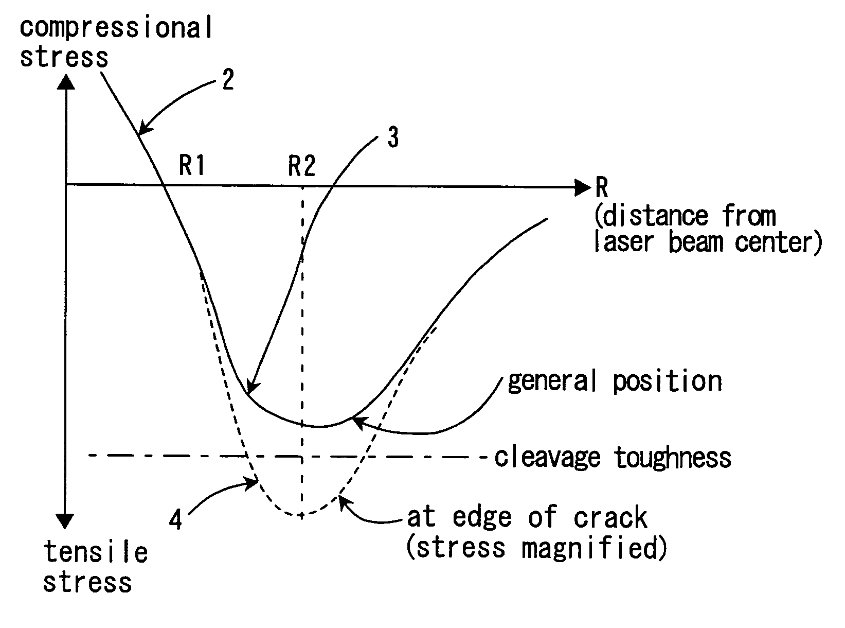
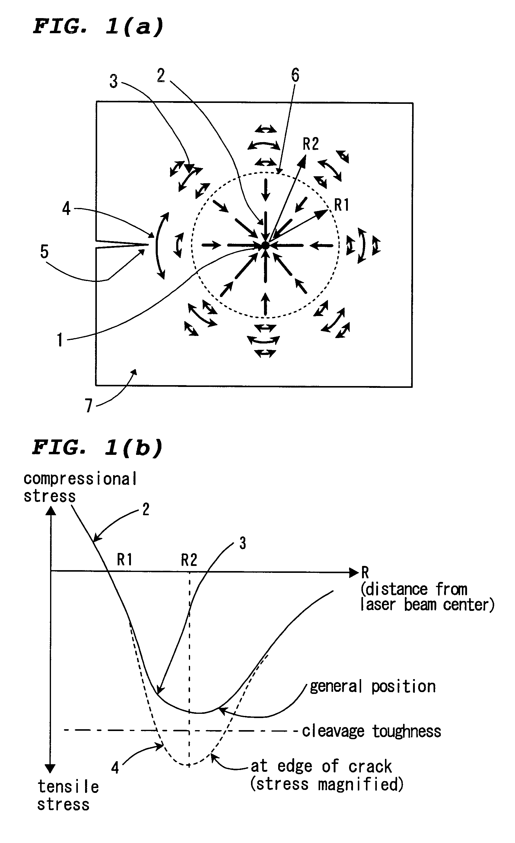
The rapid local heating invites random and irregular but mostly radially distributed cracks, which cannot realize a controlled straight line scribing in the desired direction.
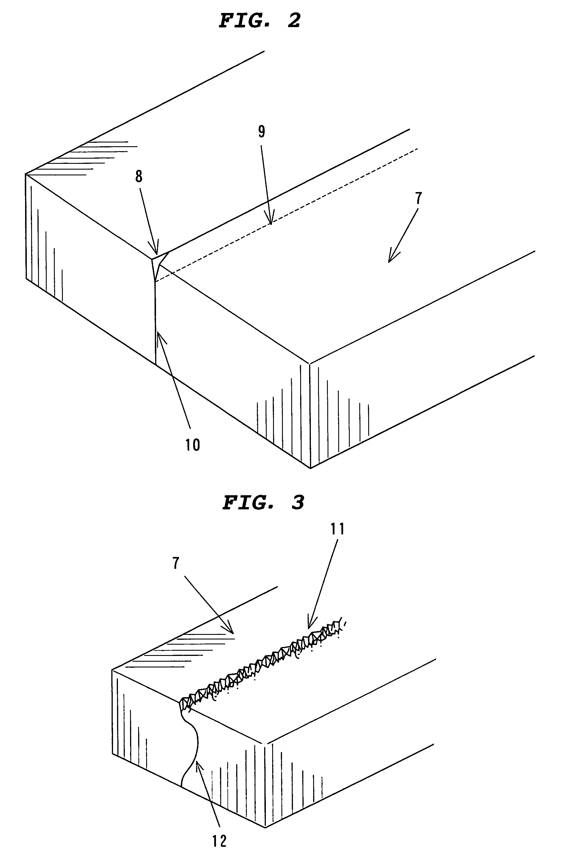
In this method, the existence of numerous micro cracks in the processed area shown in FIG. 3 enables the subsequent mechanical breaking.
The application, however, is limited due to the necessity of the subsequent breaking.
On the manufacturing floor of LC TV sets, the CO2 laser scribing method has not yet found active application.
The method solving all these problems has not yet been developed.

Method used


Image

  • Full-body laser scribing method of fragile material
  • Full-body laser scribing method of fragile material
  • Full-body laser scribing method of fragile material

Examples


first embodiment

[0039] Generally, the penetration of light within any material depends upon its absorption in it. Let's the absorption coefficient of the material be denoted by a (cm−1), propagated distance by x (cm), the beam intensity before and after the propagation by I and I0 respectively, the following relation holds.

I=I0·e−ax  (1)

[0040] From Eq. (1), the necessary absorption coefficient can be determined in relation to the expected distance. Next, the maximum, optimum and minimum values of absorption coefficient proper in this invention are calculated

[0041] The minimum value is defined by the condition that 90% of the laser beam passes through the plate of the thickness L. Here, the majority of the laser beam energy is wasted but the full-body scribing can be secured. Putting I / I0=0.9 in Eq. (1), we obtain a=0.105 / L. We define this case as the minimum value of the absorption coefficient. We have often experienced that when the laser scribing is performed up to the thickness of one fourth, w...

second embodiment

[0053] Next one example of the usefulness of selecting the wavelength is given. In the embodiment 2, the use of CO laser beam oscillating in the 5 μm band in stead of CO2 laser is explained. This laser is relatively feasible because a CO2 laser can be converted into this laser by changing the laser gas and cavity optics. A CO laser generates the beam, the wavelength of which extends in the band between 4.9 μm through 5.7 μm. According to FIG. 5 the absorption coefficient of quartz at 5 μm is 62.85 cm−1. Then according to Eq. (1), 99% of the laser beam is absorbed in the glass plate of the thickness of 0.7 mm. The full-body scribing of the glass plate 7 can be done with a CO laser, although a lower absorption coefficient is more desirable. As the thickness of the glass plate used in the LC panels decreases monotonously, this method to use a CO laser will become more useful in the future.

third embodiment

[0054] It is possible to increase the transmission of the laser beam within the glass thereby realizing an ideal full-body scribing. Glass is transparent in the visible wavelength range and generally shows absorption both in the UV ad infrared ranges. FIG. 7 shows the transmission characteristics as a function of wavelength for 0.7 mm thick non-alkaline glass which is used in LC TV. The vertical axis of this figure is the transmissivity T (%). Neglecting Fresnel reflection on the glass surface, Eq. (1) gives the value of a from the relation of T=I / I0=e−0.07a. In contrast to the case of crystal, the composition and structure of which are fixed, the composition of any commercial glass varies from manufacturer to manufacturer. We can refer to the transmission characteristics shown in FIG. 7 in the first order approximation. Then we can obtain the absorption coefficient of non-alkaline glass in the wavelength range between 2.5 μm and 4.6 μm to be 2.3 cm−1 to 40 cm−1. On the other hand, ...


PUM

PropertyMeasurementUnit
depthaaaaaaaaaa
thicknessesaaaaaaaaaa

Abstract

This invention enables the full-body (throughout the entire thickness) scribing of a plate made of fragile material such as glass by irradiating the work with the laser beam for heating with or without cooling and thereby generating the tensile thermal stress in the work which exceeds the cleavage toughness of the material, dispensing with the mechanical breaking. In this invention, the absorption of the beam in the work is so controlled that the beam, while being absorbed in it, is either transmitted through it or reaches the adequate thickness of the work and the entire thickness scribing is realized. This absorption control is done by selecting the laser beam wavelength so as to achieve the proper absorption in the absorption spectra of the material either due to the electronic transition or the lattice vibration. The doping of the material, in which the commercially available high power laser beam can be absorbed properly and either of the absorption or emission in the visible light spectral range does not exist, can also be utilized for this absorption control. In this case, the quenching of the fluorescence which may arise after the beam absorption is useful. This invention enables the profile scribing of work or the selective scribing of piled work consisting of plural number of plates.

Description

TECHNICAL FIELD [0001] This invention relates to the full-body laser scribing method of the fragile material such as glass, quartz, ceramics or semiconductor. In order to simplify the explanation, the case of processing glass is represented below. BACKGROUND TECHNIQUE [0002] The cutting of fine glass used in flat panel displays which are in liquid crystal (hereafter abbreviated as LC) TV and plasma TV sets is presently performed using the conventional mechanical method, which is not free from the various kinds of problems such as the necessity of polishing, existence of micro-crack layer, etc. [0003] The glass used in automobile, which is mostly round-shaped, requires polishing after the mechanical straight line cutting. [0004] Tempered glass used in architecture is difficult to cut mechanically and requires a new processing method. [0005] The advent of the laser technology, which can improve the quality and broaden the range of processing will be the solution to the various kinds o...

Claims


Application Information

Patent Timeline
Patent Type & Authority Applications(United States)
IPC IPC(8): B23K26/38
CPCB23K26/0604B23K26/0869B23K26/421B23K26/4075B23K26/38B23K26/60B23K26/40B23K2103/50C03B33/09
Inventor KARUBE, NORIOMIURA, HIROSHI
Owner LEMI
Why Eureka
Try Eureka