Secure and fast calculating unit

a technology of calculating unit and calculating unit, applied in the field of calculating unit, can solve the problems of insufficient security, double the power consumption of the complete circuit, and the current consumption of the entire circuit is double the amount of the total circuit, so as to achieve fast and secure calculating

Inactive Publication Date: 2007-03-22
INFINEON TECH AG
View PDF1 Cites 8 Cited by
  • Summary
  • Abstract
  • Description
  • Claims
  • Application Information

AI Technical Summary

Benefits of technology

[0028] It is the object of the present invention to provide a fast and secure calculating unit.

Problems solved by technology

The three operand adder shown in FIG. 7 is problematic in so far that neither a backup of input operands C, N, Z nor a backup of the “intermediate operands” x, y is provided.
This is problematic in so far that in particular in the normal case in which all circuits are implemented in a CMOS logic, switching a bit from 0 to 1 or from 1 to 0, respectively, leads to a current pulse which starts when a bit state is switched.
However, in the switching state they consume current.
The dual rail technology provides a high security, with the disadvantage, however, that all circuits usually have to be implemented in double and that the power consumption of the complete circuit is also double as high.
Thus, it is not sufficient for an optimum security, however, that the input lines into the elements 80 and 81 and the output lines from elements 80 and 81 are implemented in dual rail technology.
It is obvious that cryptographic calculations are extremely computing-intense.
Although this circuit already is space-efficient, as the switching stages are not implemented in a complete dual rail logic, and although this circuit is energy-efficient in so far that the switching stage always respectively only calculates the inverted bit or the bit itself, i.e., consumes no current for both bits, it has turned out anyway that there may be problems in the transition from a preparation mode to a data mode.
It further turned out, that this effect may be substantially increased by unavoidable coupling capacities, so that under especially unfavorable conditions not the driven bit but the residual charge so to speak wins and “turns around” the driven bit.
This even leads to the fact that the calculated result is wrong.

Method used


Image

  • Secure and fast calculating unit
  • Secure and fast calculating unit
  • Secure and fast calculating unit

Examples


Embodiment Construction

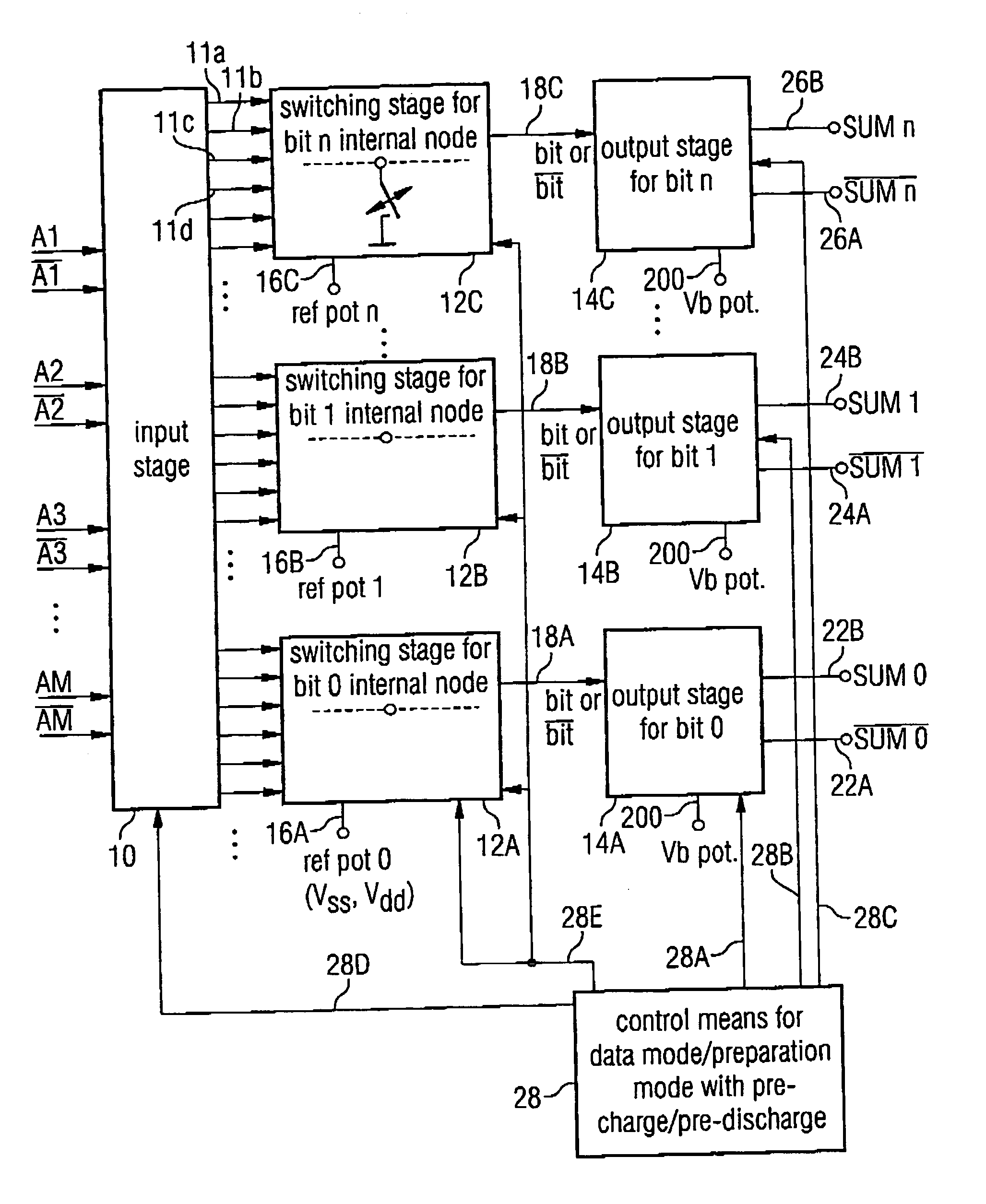
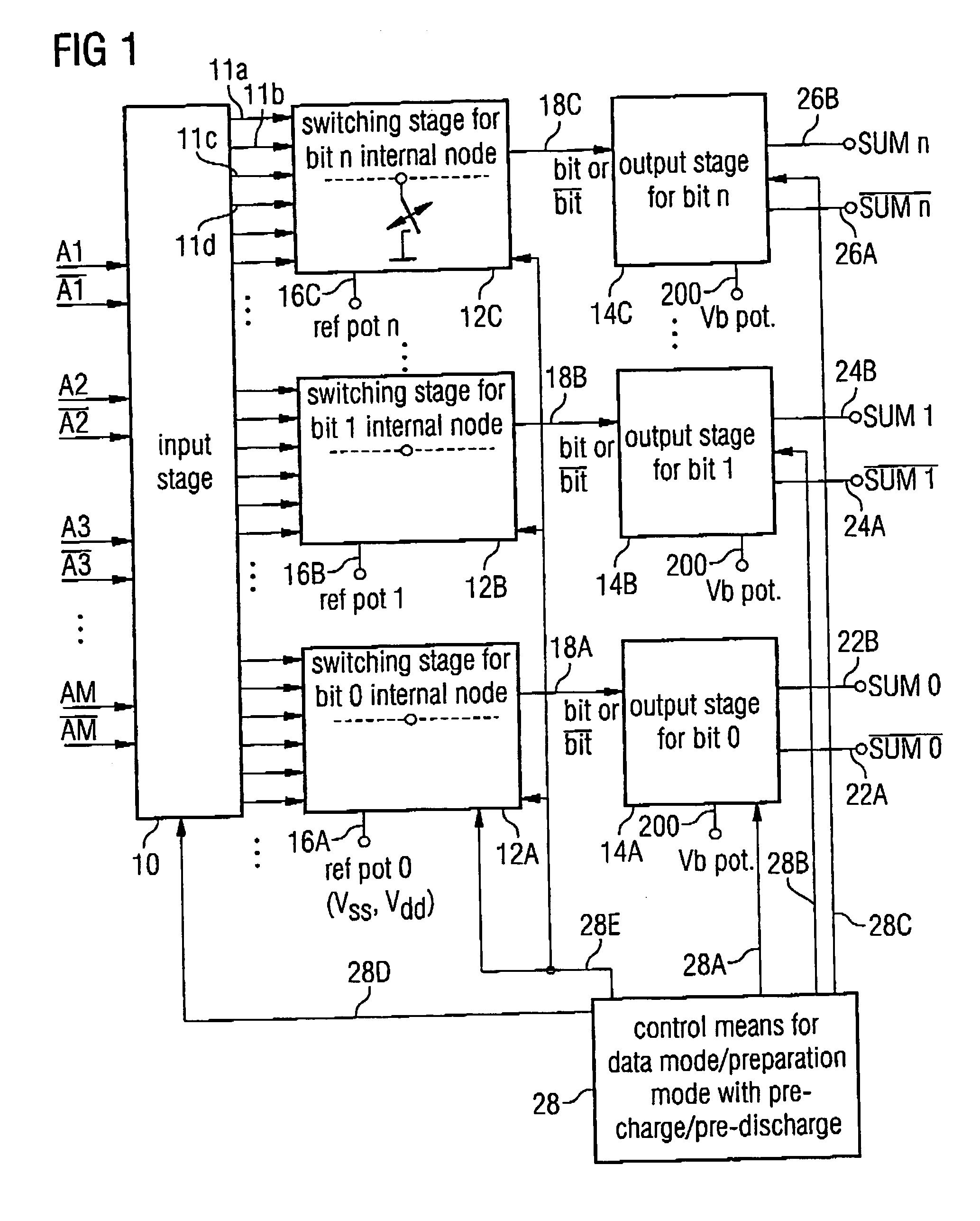
[0059] In the following, with reference to FIGS. 1 to 6C, the present invention is illustrated with reference to a half adder. It is to be noted, however, that the present invention can be applied to any calculating units which, for calculating, operate on the basis of a switching stage which is not implemented in full dual rail which calculates only one single output bit according to an adder regulation by connecting the output bit or the inverted output bit to the calculating potential, depending on the calculating regulation, while the complementary bit is then added in a corresponding output stage, i.e., is so to speak taken over from the preceding preparation clock and if applicable stabilized accordingly. In particular, the present invention may be applied in every calculating unit with such a switching stage, if the switching stage includes at least internal node which is coupled neither to a potential of the input stage nor to a potential of the output stage in the preparati...


PUM


Abstract

The calculating unit includes a dual rail input stage, a switching stage for a bit to be calculated and an output stage for an output bit, wherein the output stage provides a dual rail output. The switching stage is not implemented in dual rail technology but according to a “one-hot” realization. The switching stage includes at least one internal node which is, in the preparation mode according to a control signal on a control line from a control means, connected to a reference potential, while the node potential circuit for handling the internal node in the data mode is not active. Thus, an area-efficient, cross-current-reduced and reliable calculating unit is obtained, which may additionally be clocked at high speed, as a transition form a preparation mode to a data mode takes place without time-consuming discharge processes.

Description

CROSS-REFERENCE TO RELATED APPLICATION [0001] This application claims priority from German Patent Application No. 102005011374.5, which was filed on Mar. 11, 2005, and is incorporated herein by reference in its entirety.BACKGROUND OF THE INVENTION [0002] 1. Field of the Invention [0003] The present invention relates to calculating units and in particular to secure and fast calculating units as they may be employed in cryptography processors and in particular, in adder circuits for cryptography processors. [0004] 2. Description of Related Art [0005] DE 3631992 C2 discloses a cryptography processor for performing the RSA public key crypto system. Here, a modular exponentiation with a base, an exponent, and a module is broken down into a plurality of three operand additions. The three operands include a module operand N, a multiplicand operand C, and an intermediate result operand Z. By a corresponding shifting / weighting of the three operands before the addition a multiplication / reduct...

Claims


Application Information

Patent Timeline
Patent Type & Authority Applications(United States)
IPC IPC(8): H03F3/45
CPCG06F7/501G06F2207/7266G06F2207/3872G06F7/00
Inventor JANSSEN, NORBERTROEMER, TANJA
Owner INFINEON TECH AG
Why Eureka
Try Eureka