Data reproduction circuit

a data reproduction and clock technology, applied in digital transmission, electrical equipment, angle demodulation by phase difference detection, etc., can solve the problems of affecting the performance improvement of a computer, the transmission speed between a device and a circuit block in the chip is a big factor in restricting the chip performance, and the increase in the frequency of the clock and data, so as to reduce the amount of hardware and achieve high jitter tracking capability , the effect of easy generation

Inactive Publication Date: 2007-03-22
FUJITSU LTD
View PDF10 Cites 20 Cited by
  • Summary
  • Abstract
  • Description
  • Claims
  • Application Information

AI Technical Summary

Benefits of technology

[0034] By adopting such a configuration, detecting phase / frequency errors of phase and feeding it back to the frequency of a determination clock, input data and a sampling clock can be kept at an integral ratio. As a result, there are no overlap and missing in output obtained by over-sampling data, and there is no need for flow control.
[0035] According to the present invention, high jitter tracking capability can be obtained in over-sampling determination and also there is no need for flow control in a higher-order layer. There is no need for buffer memory for enabling flow control, thereby reducing the amount of hardware. A signal generated to adjust phase / frequency, based on a frequency / phase error can be easily generated in a control circuit for over-sampling, thereby reducing its cost increase to a minimum.

Problems solved by technology

For example, a speed gap at the time of transmission between memory, such as SRAM, DRAM or the like and a processor has a tendency to increase, and this speed gap disturbs the performance improvement of a computer.
Besides the speed gap at the time of transmission, with a larger-scaled chip in an LSI, the signal transmission speed between a device and a circuit block in the chip is a big factor in restricting the performance of the chip.
However, in the phase tracking method, although a clock with low jitters can be reproduced, the rapid fluctuation of a clock phase cannot be tracked.
However, the over-sampling method and the clock / data reproduction circuit have the following problems.
In this case, in the over-sampling method, cyclical data overlap and missing occurs in data outputted from a receiving circuit.
Such a flow control cannot be always realized by a communication protocol.

Method used


Image

  • Data reproduction circuit
  • Data reproduction circuit
  • Data reproduction circuit

Examples


Embodiment Construction

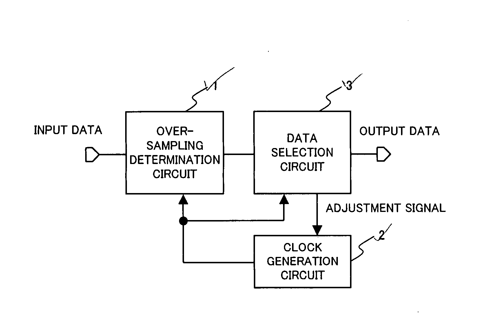
[0066] The preferred embodiments of the present invention are described in detail below with reference to the drawings. FIGS. 4A and 4B show the basic configurations of the present invention. FIG. 4A comprises an over-sampling determination circuit 1, a clock generation circuit 2 and a data selection circuit 3. FIG. 4B comprises an over-sampling determination circuit 1, a clock generation circuit A4, a clock generation circuit B5 and a data selection circuit 3.

[0067] According to the configuration shown in FIG. 4A, the phase / frequency errors and the like of input data and a sampling clock are detected and an adjustment signal is generated. Based on the adjustment signal, a clock frequency according to the size of a frequency difference is fed back. Using the clock, over-sampling is conducted.

[0068] According to the configuration shown in FIG. 4B, the phase / frequency errors and the like of input data and a sampling clock are detected and an adjustment signal is generated. Based on ...


PUM


Abstract

This is a data reproduction circuit for receiving data and reproducing the data and its clock which comprises an over-sampling determination circuit for sampling the received data by a clock with frequency higher than the data rate of the received data and converting the sampled data into digital signals, a circuit for selecting and outputting the reproduced data, a phase error detection circuit for detecting a phase error from its timing deviation with the received data, based on the reproduced clock, a data selection circuit for adjusting its phase, based on the output of the phase error detection circuit, a phase adjustment circuit for adjusting the phase of the reproduced clock to reproduce a new clock and a clock generation circuit for supplying the over-sampling determination circuit and the data selection circuit with the newly reproduced clock.

Description

CROSS-REFERENCE TO RELATED APPLICATIONS [0001] This application is based upon and claims the benefit of priority from the prior Japanese Patent Application No. 2005-271024 filed on Sep. 16, 2005, the entire contents of which are incorporated herein by reference. BACKGROUND OF THE INVENTION [0002] 1. Field of the Invention [0003] The present invention relates to reproduction of clock and data in high-speed transmission, and more particularly relates to a technology for transmitting signals between LSI chips, between a plurality of devices and circuit blocks in an LSI chip and, between boards and between cabinets at high speed. [0004] 2. Description of the Related Art [0005] Today, in order to improve the performance of a system, the performance of components composing a computer and other information processing equipment, such as static random-access memory (SRAM), dynamic random-access memory (DRAM), a processor, a switching LSI and the like, is improved. In order to improve the per...

Claims


Application Information

Patent Timeline
Patent Type & Authority Applications(United States)
IPC IPC(8): H04L7/00H03D3/24
CPCH04L7/033
Inventor TAMURA, HIROTAKA
Owner FUJITSU LTD
Why Eureka
Try Eureka