Electronic parts for high frequency power amplifier

a technology of high-frequency power amplifiers and electronic parts, which is applied in the direction of amplifiers with semiconductor devices only, amplifier protection circuit arrangements, amplifiers with semiconductor devices, etc., can solve the problems of relatively difficult to enhance a directional property and difficult to completely eliminate the influence of reflected wave propagating through the subline, so as to achieve the effect of reducing the size of the directional coupler and high accuracy

Inactive Publication Date: 2007-03-29
RENESAS TECH CORP
View PDF0 Cites 69 Cited by
  • Summary
  • Abstract
  • Description
  • Claims
  • Application Information

AI Technical Summary

Benefits of technology

[0026] That is, according to the invention, in a wireless communication system for detecting the output power and for performing the feedback control, the electronic part for the high frequency power amplifier can be achieved which enables control of the output power with high accuracy without any influence on the monitor voltage by the reflected wave propagating through the line of the directional coupler. Also, this achieves a decrease in size of the directional coupler, and consequently, in size of the electronic part (module) for the high frequency power amplifier.

Problems solved by technology

The patent inventors, however, have found that when making the high frequency power amplifier module employing the directional coupler of the prior invention to measure the monitor voltage thereof, only the adjustment of the capacitance value between the main line and the subline, and of the resistance value of the termination side of the subline makes it difficult to completely eliminate the influence of the reflected wave propagating through the subline.
Only the improvement of the coupler itself makes it relatively difficult to enhance a directional property thereof, that is, to reduce a reflected-wave component taken, while increasing a traveling-wave component.

Method used


Image

  • Electronic parts for high frequency power amplifier
  • Electronic parts for high frequency power amplifier
  • Electronic parts for high frequency power amplifier

Examples


first embodiment

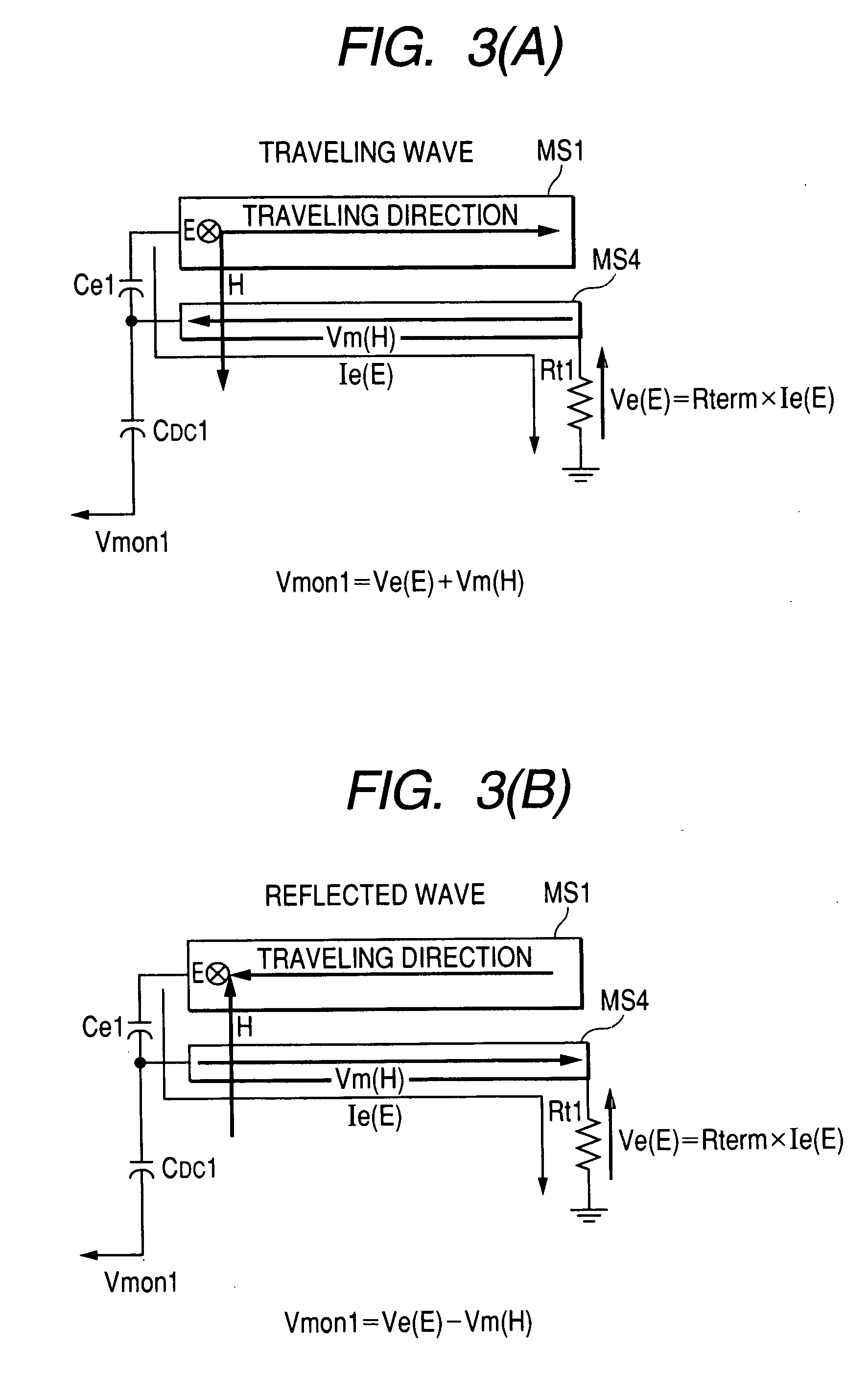
[0062] The following is a reason why the influence of the reflected wave can be reduced in the same manner as the first embodiment, which takes the reflected-wave component from the second subline, even if the reflected-wave component is taken from the termination of the microstripline MS4 serving as the subline via the coupling capacitor Ce. The reason is based on a directional property of the coupler. That is, taking into consideration the traveling wave on the main line, as shown in FIG. 8A, the beginning side of the subline MS4 is a coupled port (capacitance coupling port), and the termination side of the subline MS4 is an isolation port. In contrast, taking into consideration the reflected wave of the main line, as shown in FIG. 8B, the beginning side of the subline MS4 is an isolation port, and the termination side of the subline MS4 is a coupled port.

second embodiment

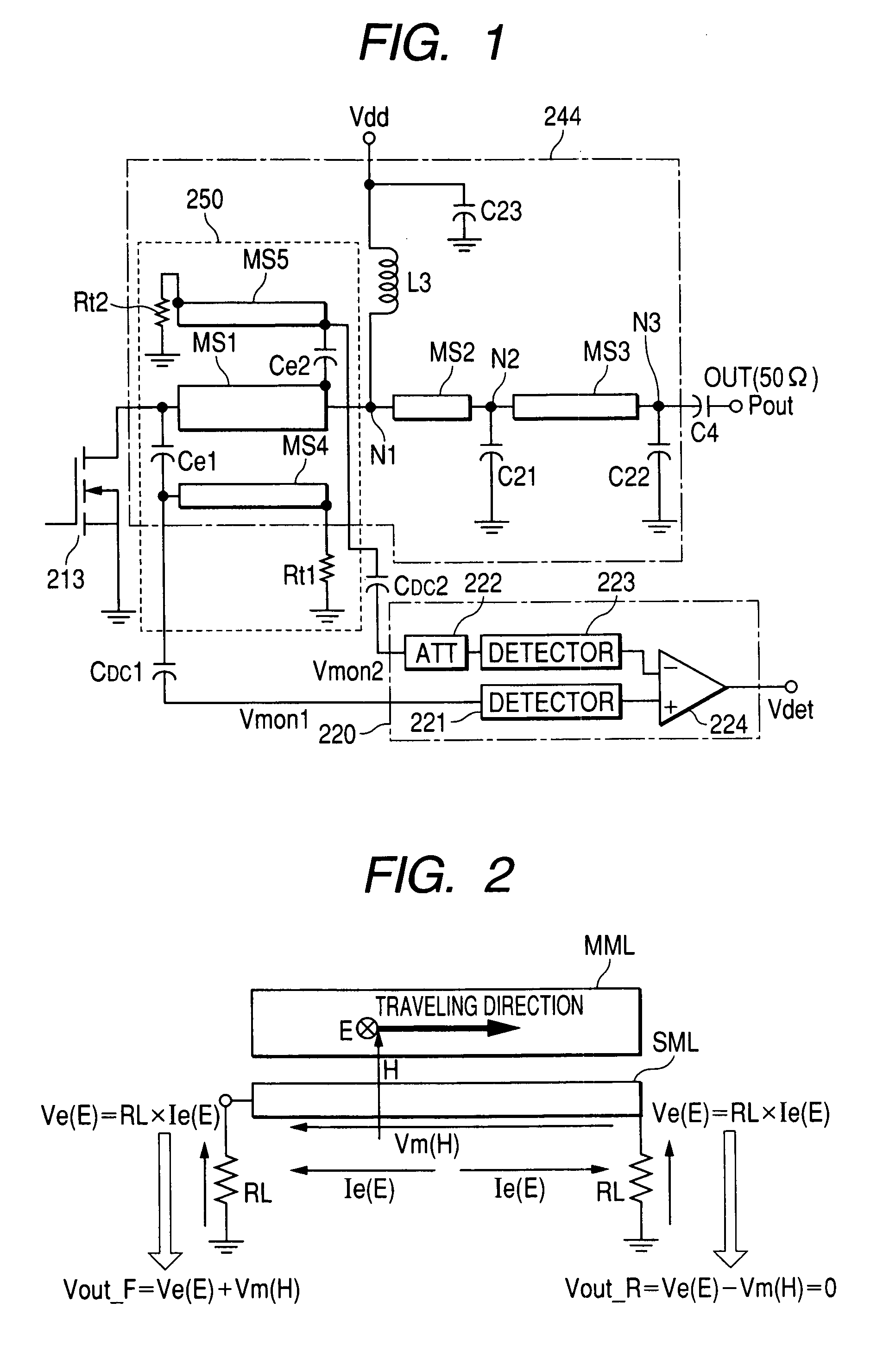
[0063]FIG. 9 shows the detailed configuration of the RF power module to which the directional coupler of the second embodiment is applied. In FIG. 9, the repeated explanation of the same circuit and element as those shown in FIG. 1 and FIG. 7 will be omitted.

[0064] An RF power module 200 of this embodiment includes a high frequency power amplifier 210 including the FET for the power amplifier for amplifying an input high frequency signal Pin modulated, and an output power detection circuit 220 for detecting an output power from the high frequency power amplifier circuit 210. The RF power module also includes a bias circuit 230 for controlling an idle current which passes through each FET by applying a bias voltage to the FET for the power amplifier at each stage of the high frequency power amplifier 210, and a power coupler 250 of the embodiment disposed between the matching circuit 244 located at the last stage of the high frequency power amplifier 210 and the output power detectio...


PUM


Abstract

An electronic part for a high frequency power amplifier is provided which is designed to constitute at least a part of a wireless communication system for performing feedback control by detecting an output power, and which can miniaturize a directional coupler. Also, the electronic part permits control of the output power with high accuracy without having any influence on a monitor voltage by a reflected wave propagating through a line of the directional coupler. The directional coupler includes a subline disposed in parallel to and in the vicinity of a part of a main line of an impedance matching circuit on the last output stage side of a power amplifier circuit, a capacitance element connected to between the main line and the subline, and a resistor element connected to between a constant potential point and a termination side of the subline. An output power detection circuit includes a first detection circuit for detecting an alternating current signal taken from a beginning side of the subline, a second detecting circuit for detecting an alternating current signal taken from a termination side of the subline, and a subtracting circuit for performing subtraction between an output of the first detection circuit and an output of the second detection circuit.

Description

CROSS-REFERENCE TO RELATED APPLICATION [0001] The present application claims priority from Japanese patent application No. 2005-281416 filed on Sep. 28, 2005, the content of which is hereby incorporated by reference into this application. BACKGROUND OF THE INVENTION [0002] The present invention relates to a technique useful for applications to electronic parts for a high frequency power amplifier which incorporates therein a high frequency power amplifier circuit to be used in a wireless communication system, such as a portable telephone or the like, for amplifying and outputting a transmission signal of high frequency, and a directional coupler to be used for detection of an output power required for feedback control of the output power. [0003] In general, an output unit on a transmission side of a wireless communication device (mobile communication system), such as a portable telephone, is provided with a high frequency power amplifier circuit for amplifying a transmission signal ...

Claims


Application Information

Patent Timeline
Patent Type & Authority Applications(United States)
IPC IPC(8): H03F1/52
CPCH03F1/301H03F1/34H03F2200/99H03F3/189H03F3/68H03F1/565
Inventor HAYATA, KANJIAKAMINE, HITOSHINAGAMORI, HIROYUKI
Owner RENESAS TECH CORP
Why Eureka
Try Eureka