[0039] The present inventions was accomplished in view of the aforementioned problems. An object of the present invention is to provide a display panel and a
display device having a high display quality with improved response speed and higher transmissivity. Moreover, another object of the present invention is to provide a display panel, which is produced without a
rubbing step thereby to prevent defects that would be caused by dusts or
high voltage static electricity caused by
rubbing process, and to reduce production cost.
[0042] As described above, in the conventional
liquid crystal display element, the display operation is carried out by utilizing only the change in the orientation direction of the liquid
crystal molecules due to rotation thereof caused by the electric field application. The liquid
crystal molecules in alignment are rotated together in one direction. Thus,
inherent viscosity of the liquid crystal largely affects responding speed. On the other hand, the present invention, in which the display is carried out by utilizing the change in the modulation of the
optical anisotropy in the medium, is free from the problem that the
inherent viscosity of the liquid crystal largely affects responding speed, unlike the conventional
liquid crystal display element. Thus, it is possible to realize high-speed responding. Moreover, the high-speed responding allows the display element to be used, for example, in a
display device of the field sequential color mode.
[0043] Moreover, in the display panel of the present invention, the medium is optically isotropic when no electric field is applied, and becomes optically anisotropic when an electric field applied thereon. In this specific case, the shape of the
refractive index ellipsoid is spherical when no electric field is applied thereon, and is changed to elliptical shape when an electric field is applied thereon. This allows performing display by changing the magnitude (orientational order,
refractive index) of the
optical anisotropy, thereby attaining wider viewing angle property and higher speed response property than the conventional
liquid crystal display element in which the display is performed by changing the orientation direction of the liquid crystal molecules.
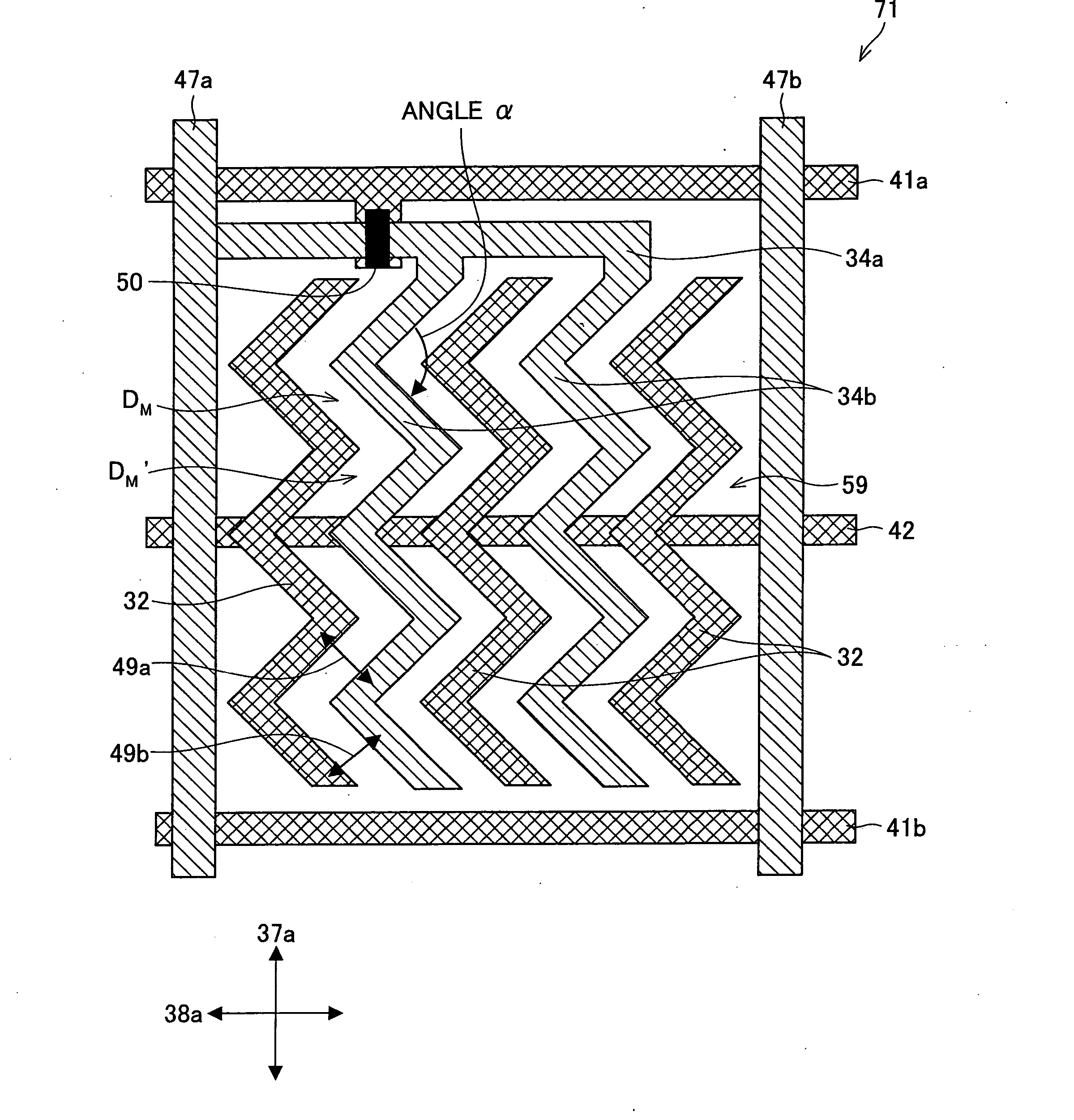
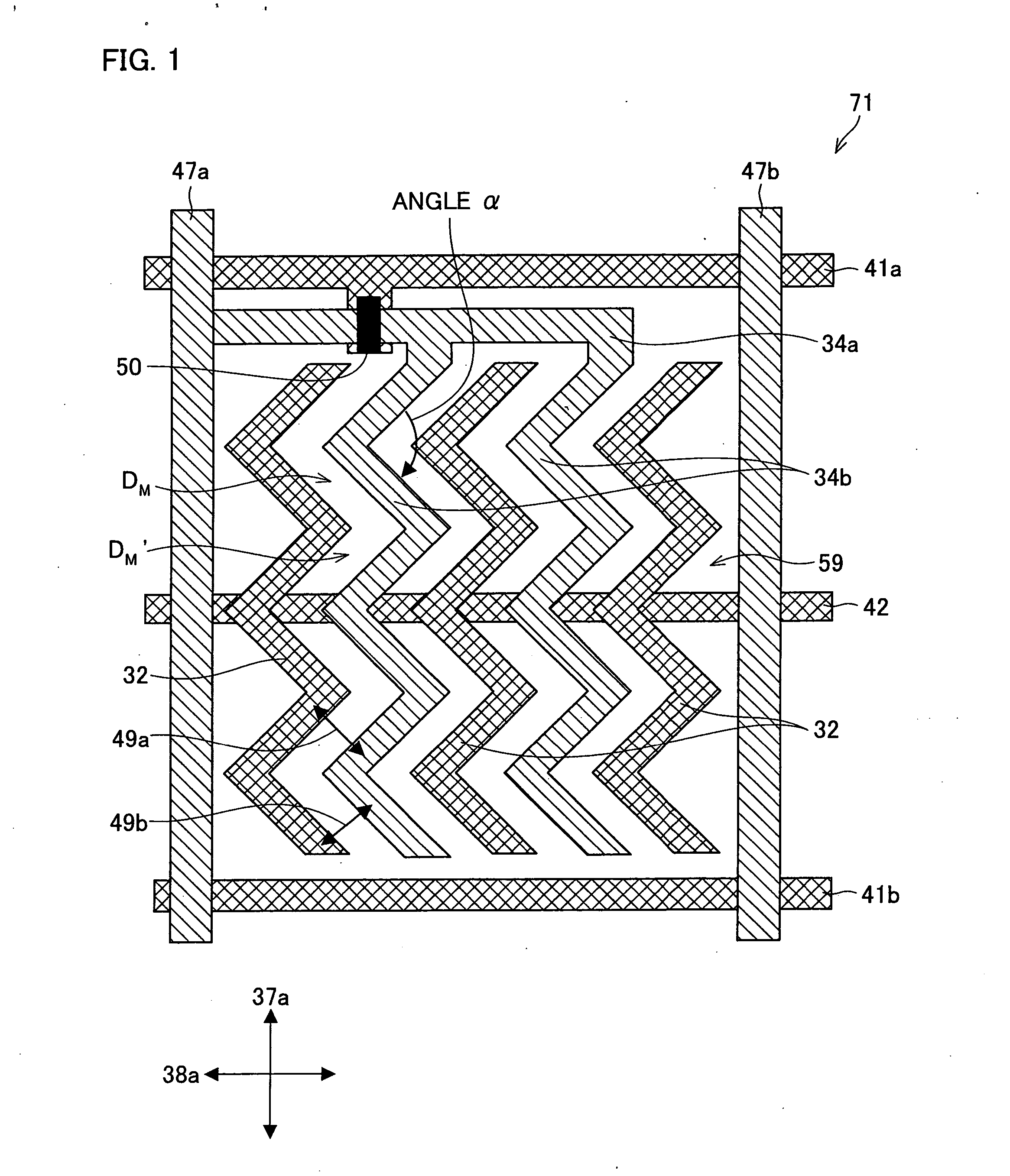
[0044] Moreover, the display panel of the present invention is configured such that and the first and the second electrodes are transparent electrodes, and a distance between the first and second electrodes is shorter than a distance between the first substrate and second substrate. This configuration allows a fringe electric field to occur between the first and second electrodes, thereby making it possible to change the magnitude of the optical
anisotropy of the medium in the regions above the electrodes (i.e., regions that overlap the first and second electrodes when viewed in the normal direction of the substrate plane). This allows the regions above the electrodes to be utilized as display regions and to contribute to transmissivity. Thus, this improves transmissivity.
[0045] Unlike the conventional liquid
crystal display elements using IPS mode or FFS mode, the medium used in the liquid crystal panel of the present invention is optically isotropic when no electric field is applied thereon, and becomes optically anisotropic when an electric field is applied thereon. Therefore, there is no need of aligning by using an alignment film, the liquid crystal molecules so as to specify the alignment that the liquid crystal molecules have when no electric field is applied, unlike the conventional liquid
crystal display elements. Thus, the alignment film is not essential in the display panel of the present invention. On this account, alignment process such as
rubbing alignment process etc. is not necessary in the present invention. In the rubbing step, the alignment film made of a
polymer such as
polyimide is rubbed with a cloth or the like. Thus, the rubbing step is associated with fine dust and fine
electric discharge (local
discharge) which occurs due to
high voltage static electricity. The dusts are a big problem in highly fine pixel electrodes and TFT forming process in which film deposition,
exposure, and
etching are repeated. The local
electric discharge would damage the alignment film, or cause disconnection or
electrostatic discharge damage in TFT and transparent
electrode such as ITO. In the display panel of the present invention, the rubbing alignment process, which is carried out in the conventional liquid
crystal display elements, can be omitted. Thus, it is possible to prevent the problems of dust and local
discharge, which are caused by the rubbing alignment process. Further, the omission of the alignment process step such as rubbing reduces production cost.
[0046] Compared with the conventional liquid crystal materials, a correlation distance in orientation change is short in the medium that is optically isotropic when no electric field is applied and whose magnitude of optical
anisotropy is changeable by and according to the electric field applied thereon. Because of this, even if a large electric field is generated locally in the vicinity of an edge of the electrodes, orientation disturbance due to the large electric field will not be transmitted in a long distance. Therefore, the display panel of the present invention has a better prevention for deterioration in the display performance, which is caused by orientation disturbance, compared with the conventional liquid crystal display devices.

