Methods and Apparatus for the On-Site Production of Hydrogen Peroxide

a hydrogen peroxide and onsite technology, applied in the direction of electrolysis components, chemistry apparatus and processes, treatment water, etc., can solve the problems of not being widely used for industrial sterilization, cost and safety of traditional (chemical) hydrogen peroxide sources, and not allowing pure hydrogen peroxide to be generated directly in liquid streams, etc., to achieve low cost hydrogen peroxide production, tighten waste disposal emission constraints, and reduce health, safety and environmental risks

Inactive Publication Date: 2007-04-05
ELTRON RES
View PDF57 Cites 55 Cited by
  • Summary
  • Abstract
  • Description
  • Claims
  • Application Information

AI Technical Summary

Benefits of technology

[0015] An objective of the invention is to generate disinfectant solutions containing concentrations of hydrogen peroxide sufficient to be effective against a wide variey of organisms. In an embodiment, as much as 1000 ppm hydrogen peroxide may be generated, and be effective against a wide variety of microorganisms. Producing these levels of peroxide with the disclosed methods and apparatus is efficient. For example, hydrogen peroxide produced by an embodiment of the electrolytic technology described herein may cost only about 1 / 10th that of hydrogen peroxide produced by the common bulk production process based on anthraquinone auto oxidation. While the pH shifts developed by this technology are significant and will aid the disinfection, the concentrations will still be 3-4 orders of magnitude safer than concentrated sources of cleansers used in traditional dilution dosing schemes. Thus the proposed methods and apparatus are not only convenient, low-cost, and environmentally gentle, they are also significantly safer than alternative existing technologies.
[0016] Potential applications of the described methods and apparatus include cleansing, microbial control, value-added chemical processes, and advanced oxidation processes for chemical degradation. The areas of sterilization and environmental reclamation provide the most obvious potential markets, particularly as a replacement for the use of chlorinated compounds in the former. The technology has been shown to be effective in treatment of liquid streams. The treatment of cooling tower water to control microbial buildup as well as treatment of ship ballast water for reduction of non-native organisms are two applications that have received much attention. The treatment of infectious waste liquid streams generated at medical facilities has become a significant market with tightening constraints on waste disposal emissions. Competitive advantages of this electrolytic technology include adaptability to both small and large scale treatment volumes, on site and on demand treatment, and low cost hydrogen peroxide production. Additionally, the point of use generation of an environmentally gentle oxidant obviates the need for transport and storage of concentrated hydrogen peroxide thus reducing health, safety, and environmental risks.

Problems solved by technology

Hydrogen peroxide (H2O2) has long been known as an antiseptic but has not been widely used for industrial sterilization largely due to cost.
The main drawbacks to traditional (chemical) sources of hydrogen peroxide are cost and safety.
This approach does not permit pure hydrogen peroxide to be generated directly in liquid streams because the direct required contact between oxygen and antharhydroquinone contamninates the hydrogen peroxide with the quinone and the products of its oxidation and degradation.
This leads to substantial expenses for transportation and storage.
First, strong chemicals must be manually handled and stored in concentrated form on site, posing an occupational hazard to workers.
Third, discharges of residual chlorine into the environment are now known to be harmful due to its high reactivity, which results in the formation of toxic and potentially carcinogenic chlorinated disinfection byproducts (e g, trihalomethanes, haloacetic acids).

Method used


Image

  • Methods and Apparatus for the On-Site Production of Hydrogen Peroxide
  • Methods and Apparatus for the On-Site Production of Hydrogen Peroxide
  • Methods and Apparatus for the On-Site Production of Hydrogen Peroxide

Examples


example 1

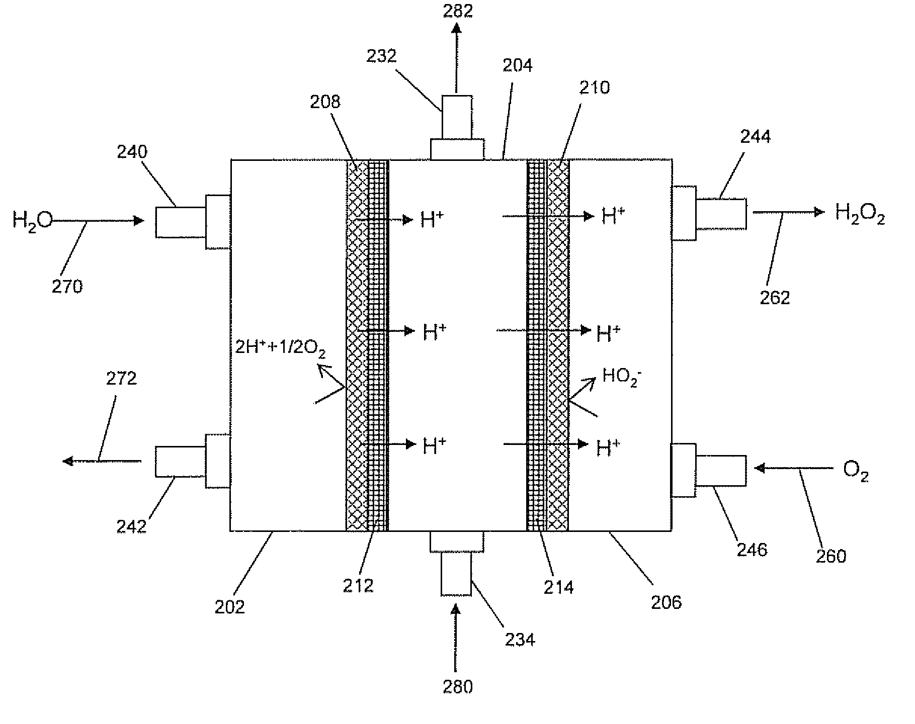
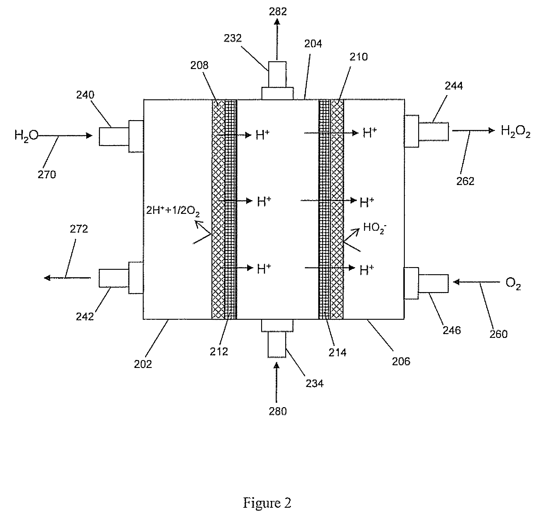
Micro-Flow Electrolytic Cell Design

[0082] In this example, the micro-flow cell was designed to have a geometric electrode area of 47 cm2. It was used to prove hydrogen peroxide production is effective in the three-chamber configuration (in contrast to two-chambers) and to determine effects of electrolyte concentrations on performance. The overall dimensions of the cell when assembled were 5.25″×6.5″×2.625″. Quick disconnect fittings were used on the catholyte (0.75″ NPT) and anolyte (0.5″ NPT) inlets and outlets. The central chamber used 0.375″ compression fittings adapted down to a #10-32 thread due to the narrow width of the central chamber flow frame.

Cathode Preparation (Micro-flow Cell)

[0083] The cathode was constructed of commercially available carbon cloth (De-Comp Composites 3k plain weave carbon cloth, FG-3k) that was mounted in a polycarbonate frame. This frame was face sealed with Viton gaskets in the cell.

[0084] The carbon cloth cathode was made by sandwiching the ca...

example 2

3 Chamber Electrolytic Cell Performance Optimization

[0136] The performance of the three chamber micro-flow electrolytic cell was evaluated. The primary goal was to identify and to optimize the most influential parameters on production. This task was performed in three stages. The first was establishing base-line cell performance and experimental techniques with the three chamber micro-flow cell. The second stage was testing the effects of different experimental parameters using the three chamber micro-flow cell. The third stage was testing the most favorable conditions to achieve the application requirements of this program with the 2x cell. Results for each of these stages are presented below after describing the experimental setup.

1. Experimental Setup and Procedures

[0137] Each chamber of the cell was plumbed into a reservoir and the reservoir contents circulated through the cell by either a high flow March pump (model TE-5C-MD) with polypropylene pump head (Centennial Equipme...

example 3

Dairy Filter Cleaning Evaluation

[0167] The objective of this task was to evaluate the viability of cleaning filtration membranes used for dairy processing with cleansing solutions produced by the electrolytic cell. Cleaning performance of the electrolytic cell-produced cleansers is compared to the performance of a commercial cleanser product line designed for this application. Simulated cleanser solutions (that mimic potential electrolytic cell product solutions) are also evaluated for comparison. The primary challenge in this task was to determine cleanser solutions that the electrolytic technology can produce that perform equally as well as the commercial cleansers.

1. Experimental Setup

[0168] The primary component of the filtration apparatus used for evaluating membrane fouling and cleansing behavior was a miniature filtration membrane cell produced by Osmonics, Inc. (Sepa CF Membrane Cell) for testing and filtering with small RO / NF / UF membranes in a cross-flow configuration s...


PUM

PropertyMeasurementUnit
Molar concentrationaaaaaaaaaa
pHaaaaaaaaaa
pHaaaaaaaaaa

Abstract

Methods, apparatus, and applications for the on-site production of hydrogen peroxide are described. An embodiment of the apparatus comprises at least one anolyte chamber coupled to at least one anode, at least one catholyte chamber, wherein the at least one catholyte chamber is coupled to at least one cathode, at least one anode membrane and at least one cathode membrane, wherein the anode membrane is adjacent to the at least one anode, wherein the cathode membrane is adjacent to the at least one cathode, at least one central chamber disposed between the at least one anolyte chamber and the at least one catholyte chamber. Hydrogen peroxide is produced by reduction of an oxygen-containing gas at the cathode.

Description

CROSS-REFERENCE TO RELATED APPLICATIONS [0001] Not applicable STATEMENT REGARDING FEDERALLY SPONSORED RESEARCH OR DEVELOPMFNT [0002] This invention was made with U.S. government support under USDA Contract No. 2002,33610-11793, NASA Contract No. NAS 9-99141, EPA Contract No. 68-D-02-052, and USDA Contract No. 2003-33610-14035. The U.S. Government has certain rights in this invention. BACKGROUND [0003] 1. Field of the Invention [0004] This disclosure relates generally to the field of hydrogen peroxide production. More specifically, this disclosure relates to methods and apparatus for the on-site and in-situ production of hydrogen peroxide. [0005] 2. Background of the Invention [0006] Hydrogen peroxide (H2O2) has long been known as an antiseptic but has not been widely used for industrial sterilization largely due to cost. It also typically requires significantly higher dosage levels than chlorine for similar activity. In light of the tightening regulation of chlorinated compounds, ho...

Claims


Application Information

Patent Timeline
Patent Type & Authority Applications(United States)
IPC IPC(8): C25B1/30
CPCC02F1/4672C02F1/722C02F2103/008C02F2201/46115C25B1/30
Inventor BUSCHMANN, WAYNE E.JAMES, PATRICK I.
Owner ELTRON RES
Why Eureka
Try Eureka