Motor modules for linear and rotary motors

a technology of motor modules and rotary motors, applied in the direction of magnetic circuit rotating parts, magnetic circuit shapes/forms/construction, windings, etc., can solve the problems of instability of motor operation, low efficiency, poor thermal dissipation properties, etc., to facilitate the reduction of the length of magnetic flux paths, improve efficiency, and reduce the effect of magnetic loss

Active Publication Date: 2007-04-05
REGAL BELOIT AMERICA
View PDF14 Cites 15 Cited by
  • Summary
  • Abstract
  • Description
  • Claims
  • Application Information

AI Technical Summary

Benefits of technology

[0008] Advantageously, the angled magnetic surfaces and / or angled flux interaction surfaces facilitate reducing the length of magnetic flux paths and / or straightening those paths through the field pole members. In some embodiments, the field pole members implement substantially straight paths to provide a relatively low magnetic reluctance flux path inside the field pole members, as compared to conventional magnetic return path designs that require magnetic flux to turn sharply, such as at an angle of ninety-degrees or greater, to enter or exit field pole regions. Further, substantially straight field pole members can also provide relatively short magnetic flux path portions between air gaps in some embodiments. As such, the combination of the groups of field pole members, the first array of magnets, and the second array of magnets can form either a linear motor or a rotary motor that operates with low magnetic losses and increased efficiency.
[0009] In at least one embodiment, the electrodynamic machine excludes back-iron as a return path for any portion of a flux path associated with a group of the field pole members, thereby increasing either torque per unit volume of a rotary motor or increasing actuation force per unit volume of a linear actuator. Excluding back-iron also enhances efficiency per unit size (or unit weight) as well as reduces manufacturing costs. In another embodiment, at least one of the field pole members is substantially straight. Substantially straight field pole members can provide a relatively short magnetic flux path between the magnets, which, in turn, may be accompanied by a reduction in the volume of magnetically permeable material as compared to the use of back-iron in some traditional stator structures. Elimination of back-iron also reduces the volume of magnetically permeable material through which magnetic flux is conducted, thereby decreasing hysteresis losses and eddy current losses (collectively known as “core losses”) as well as decreasing the amount of the materials used for manufacturing a linear or rotary motor in accordance with the various embodiments of the invention.

Problems solved by technology

While traditional linear and large rotary motor structures are functional, they have several drawbacks in their implementation.
Other drawbacks of conventional moving coil linear motors include poor thermal dissipation properties and relatively high bias forces, which are created by the current-carrying lead wires and cables.
But moving magnet linear motors have several drawbacks, too.
For example, the positioning of the magnets relative to back-iron structures can contribute to some instability in motor operation, such as cogging.
Another drawback is that the movements of the magnet structure can temporarily magnetize back-iron structures.
A drawback to this approach is that additional materials are consumed in forming larger motor structures to accommodate the larger torque arm distance, such as those structures that are used to form magnetic flux return paths.
By adding back-iron to complete a magnetic circuit, the magnetic material volume through which the magnetic flux passes increases, which detrimentally tends to increase the hysteresis and eddy current losses, both of which can be collectively referred to as “core losses.” Further, the addition of back-iron to complete a magnetic circuit increases the length of the magnetic flux path, thereby exacerbating core losses.
Another drawback to motors of this type is that the motor volume increases as the magnetic poles are positioned farther from the shaft, which in turn, limits the available applications and uses for this type of motor.
Further, “back-iron” structures are not generally formed to accept an associated ampere-turn generating element, such as one or more coils.

Method used


Image

  • Motor modules for linear and rotary motors
  • Motor modules for linear and rotary motors
  • Motor modules for linear and rotary motors

Examples


Embodiment Construction

Definitions

[0020] The following definitions apply to some of the elements described with respect to some embodiments of the invention. These definitions may likewise be expanded upon herein.

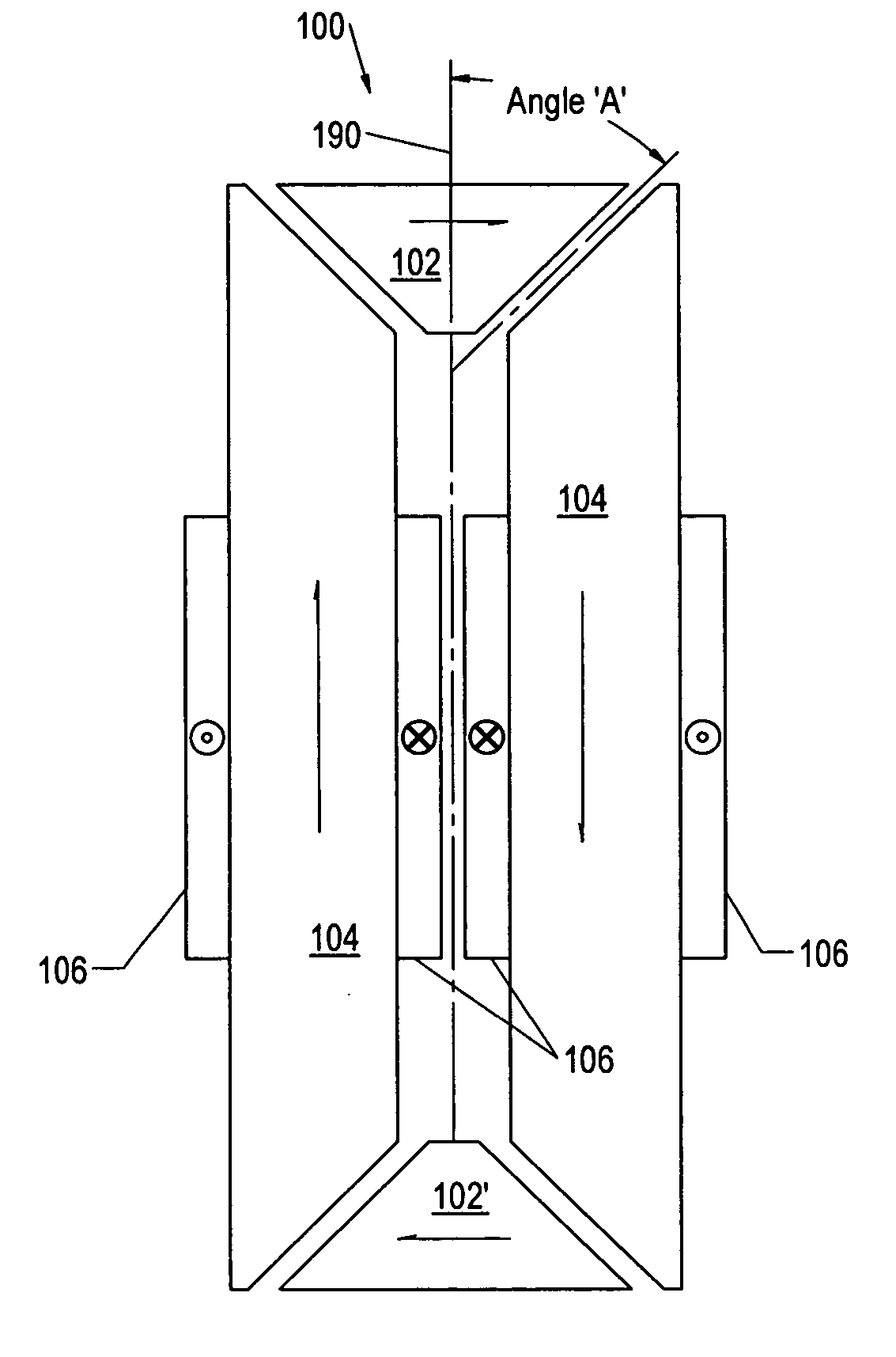
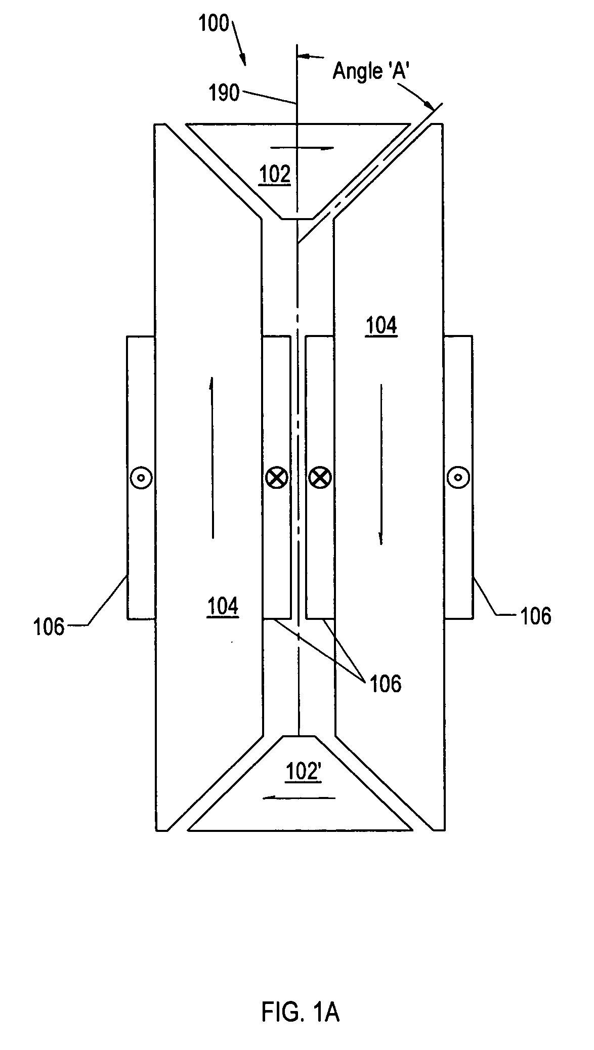
[0021] As used herein, the term “air gap” refers to a space, or a gap, between a magnet surface and a confronting pole face. Such a space can be physically described as a volume bounded at least by the areas of the magnet surface and the pole face. An air gap functions to enable relative motion between a rotor and a stator, and to define a flux interaction region. Although an air gap is typically filled with air, it need not be so limiting.

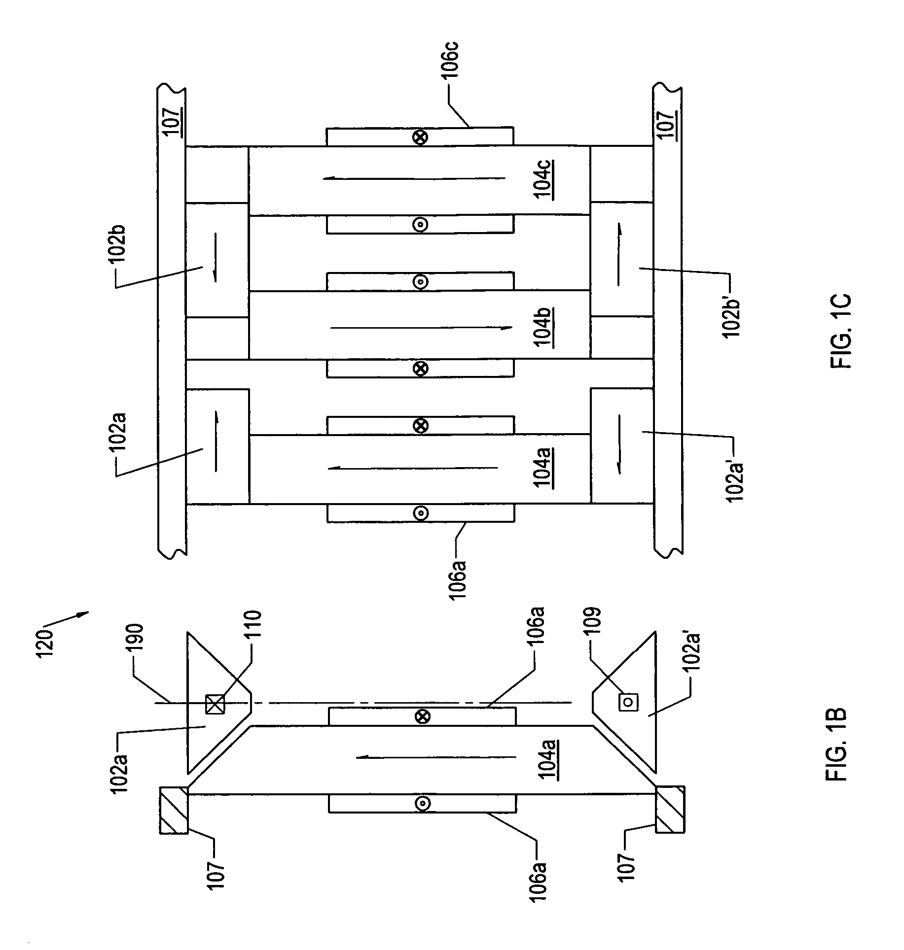
[0022] As used herein, the term “back-iron” commonly describes a physical structure (as well as the materials giving rise to that physical structure) that is often used to complete an otherwise open magnetic circuit. In particular, back-iron structures are generally used only to transfer magnetic flux from one magnetic circuit element to another, such as eit...


PUM


Abstract

A motor module, method, apparatus and system for implementing linear and rotary motors, such as relatively large rotary motors, are disclosed. In one embodiment, an electrodynamic machine can include magnets having angled magnetic surfaces and regions of predetermined magnetic polarization. The magnets can include a first array and a second array of magnets arranged in a direction of motion. Also included are groups of field pole members arranged adjacent to the first array and the second array of magnets. The field pole members include angled flux interaction surfaces, which can be formed at the ends of the field pole members to confront the angled magnetic surfaces. In combination, the angled flux interaction surfaces and the angled magnetic surfaces define air gaps. As such, the angled flux interaction surfaces are configured to magnetically couple the field pole members to the magnets to form either a linear or rotary motor.

Description

CROSS REFERENCE TO RELATED APPLICATIONS [0001] This application claims the benefit of U.S. Provisional Application No. 60 / 724,053, entitled “Motor Modules for Linear and Rotary Motors” and filed on Oct. 5, 2005 with Attorney Docket No. QUIZ-005 / 00US, the disclosure of which is incorporated herein by reference in its entirety. This application also incorporates by reference the following applications in their entirety for all purposes: (1) U.S. Provisional Application No. 60 / 622,258, entitled “Rotor-Stator Structure for Electric Motors and Generators,” filed on Oct. 25, 2004; (2) U.S. Nonprovisional Application No. 11 / 021,417, entitled “Rotor-Stator Structure for Electrodynamic Machines,” filed on Dec. 23, 2004 and issued as U.S. Pat. No. 7,061,152 on Jun. 13, 2006; (3) U.S. Nonprovisional Application No. 11 / 255,404, entitled “Rotor-Stator Structure for Electrodynamic Machines,” filed on Oct. 20, 2005 with Attorney Docket No. QUIZ-001 / 02US; and (4) U.S. Provisional Application No. 60...

Claims


Application Information

Patent Timeline
Patent Type & Authority Applications(United States)
IPC IPC(8): H02K41/00H02K23/02H02K1/12
CPCH02K21/12H02K21/24H02K41/03H02K2201/12
Inventor PETRO, JOHN PATRICKWASSON, KEN GEORGE
Owner REGAL BELOIT AMERICA
Why Eureka
Try Eureka