Switching power supply unit

a power supply unit and switching technology, applied in the direction of fixed transformers, mutual inductances, fixed transformers, etc., can solve the problems of reducing efficiency, and achieve the effect of reducing efficiency and increasing line capacitance between primary windings and secondary windings

Active Publication Date: 2007-04-05
TDK CORPARATION
View PDF6 Cites 13 Cited by
  • Summary
  • Abstract
  • Description
  • Claims
  • Application Information

AI Technical Summary

Benefits of technology

[0007] In view of foregoing, it is desirable to provide a switching power supply unit, in which core loss in the transformer or a value of heating due to AC resistance of the transformer can be decreased by reducing ringing generated in the output AC voltage of the transformer.
[0009] In the first switching power supply unit of an embodiment of the invention, strength of magnetic coupling of the first primary-winding group and the second primary-winding group to the secondary-winding group is changed in phases opposite to each other in a time-divisional manner. At that time, current direction is opposite to each other in principle of the transformer between the first primary-winding group or the second primary-winding group, and the secondary-winding group. Accordingly, AC resistance is decreased in a winding group being more strongly magnetically coupled with the secondary-winding group among the primary-winding group because influence of a proximity effect is reduced, compared with a case that winding groups having the same current direction are approximated to each other. On the other hand, AC resistance is increased due to the proximity effect in a winding group being more loosely magnetically coupled with the secondary-winding group among the primary-winding group, compared with the winding group being more strongly. magnetically coupled with the secondary-winding group among the primary-winding group.
[0023] According to the first and second switching power supply unit of the embodiment of the invention, since the first primary-winding group and the second primary-winding group, which have different strength of magnetic coupling with the secondary-winding group from each other, are connected in series to each other, ringing generated in an output AC voltage of the transformer is attenuated by AC resistance of a winding group having higher AC resistance among the primary-winding group. Thus, core loss in the transformer or a value of heating due to AC resistance of the transformer is decreased, consequently efficiency is improved.
[0024] According to the third and fourth switching power supply unit of the embodiment of the invention, since the first primary-sub-winding group and the second primary-sub-winding group, which have different strength of magnetic coupling with the secondary-winding group from each other, are connected in series to each other, and the third primary-sub-winding group and the fourth primary-sub-winding group, which have different strength of magnetic coupling with the secondary-winding group from each other, are connected in series to each other, ringing generated in an output AC voltage of the transformer is attenuated by AC resistance of a winding group having higher AC resistance among the primary-winding group. Thus, core loss in the transformer or a value of heating due to AC resistance of the transformer is decreased, consequently efficiency is improved.

Problems solved by technology

There has been a difficulty that when the ringing having the large amplitude is generated in this way, core loss in the transformer or a value of heating due to AC resistance of the transformer is increased, consequently efficiency is reduced.

Method used


Image

  • Switching power supply unit
  • Switching power supply unit
  • Switching power supply unit

Examples


second embodiment

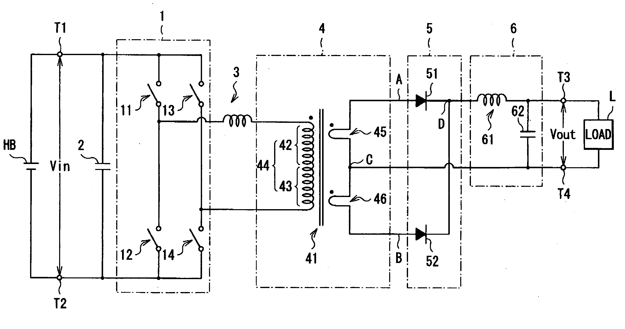
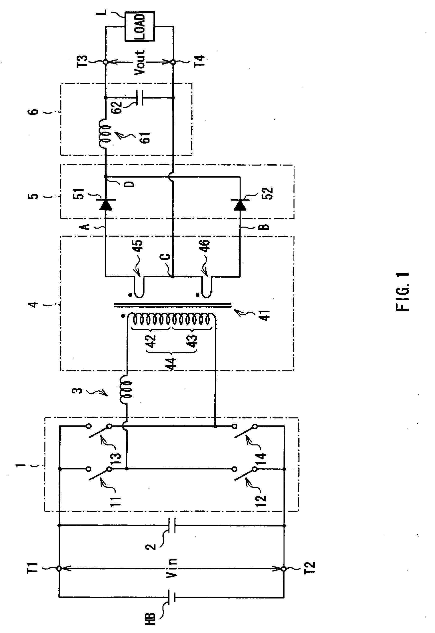
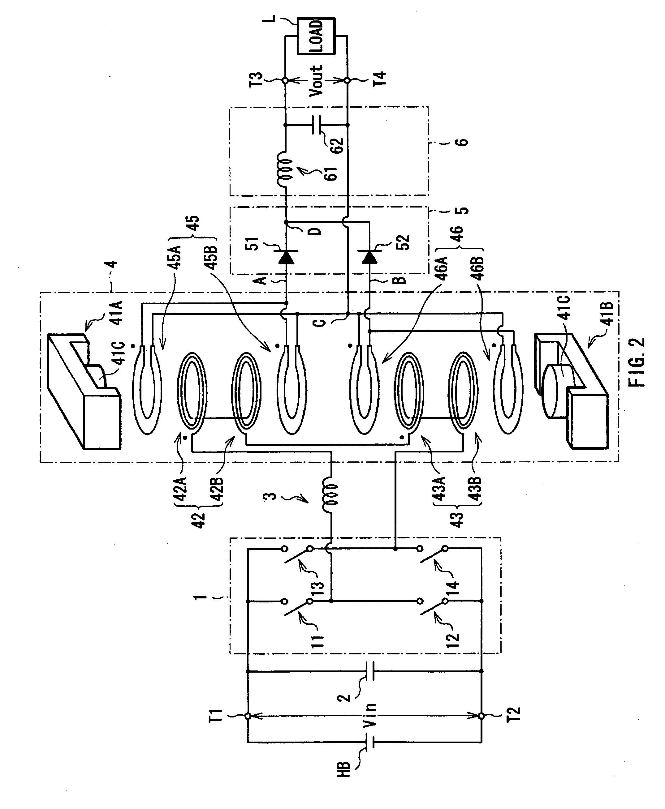
[0096]FIG. 20 shows a circuit configuration of a switching power supply unit according to a second embodiment of the invention. FIG. 21 shows a structure of a transformer in the switching power supply unit of FIG. 20 in an exploded manner. The switching power supply unit is different from the first embodiment in a configuration of an inverter circuit 10, a connection relationship between the inverter circuit 10 and a transformer 40, and a configuration of the transformer 40. Thus, different points from the first embodiment are mainly described hereinafter, and configurations, operation, and effects common to the first embodiment are appropriately omitted to be described.

[0097] The inverter circuit 10 is a push-pull type switching circuit including two switching elements 15 and 16 connected in parallel, the switching elements 15 and 16 being driven according to a switching signal supplied from a control circuit (not shown).

[0098] The transformer 40 is configured by stacking respect...


PUM

PropertyMeasurementUnit
frequencyaaaaaaaaaa
currentaaaaaaaaaa
currentaaaaaaaaaa

Abstract

A switching power supply unit is provided, in which core loss in a transformer or a level of heating due to AC resistance of the transformer can be reduced. A switching power supply unit has a transformer, an inverter circuit and a rectifier circuit. In a secondary side of the transformer, secondary wirings are connected to each other. In a primary side of the transformer, primary wirings are connected in series to each other, and connected to the inverter circuit to allow them to be driven in a time-divisional manner in phases opposite to each other in response to operation of the inverter circuit. The rectifier circuit has diodes connected to the secondary wirings to allow the secondary wirings to be driven in a time-divisional manner in phases opposite to each other in response to operation of the inverter circuit.

Description

BACKGROUND OF THE INVENTION [0001] 1. Field of the Invention [0002] The present invention relates to a switching power supply unit transforming an input AC voltage obtained by switching an input DC voltage by a transformer, and outputting an output DC voltage obtained by rectifying and smoothing the transformed output AC voltage, and particularly relates to a switching power supply unit preferably applicable using high switching frequency. [0003] 2. Description of the Related Art [0004] Hitherto, various types of switching power supply units have been proposed and provided for practical use. As one of the units, a type is given, in which an input DC voltage from a high-voltage battery is switched by switching operation of a switching circuit connected to an input winding of a transformer, an input AC voltage obtained by switching is inputted into the input winding of the transformer, and output AC voltage transformed by the transformer is drawn out from an output winding of the tran...

Claims


Application Information

Patent Timeline
Patent Type & Authority Applications(United States)
IPC IPC(8): H01F21/00
CPCH02M3/335H02M7/003H01F30/10H01F2027/348
Inventor NAKAHORI, WATARU
Owner TDK CORPARATION
Why Eureka
Try Eureka