Amplifier systems with low-noise, constant-transconductance bias generators

Active Publication Date: 2007-04-05
ANALOG DEVICES INC
View PDF7 Cites 10 Cited by
  • Summary
  • Abstract
  • Description
  • Claims
  • Application Information

AI Technical Summary

Benefits of technology

[0012] The present invention is directed to amplifier system embodiments that include bias generators which improve system performance without significantly increasing system size and/or power consumption. The no

Problems solved by technology

These generators have generally failed to effectively control at least one contributing source of error in amplifier performance.
This causes at least one bias transistor to exhibit a “body effect” which alters its threshold voltage VTH so that its drain current is no longer a reliable function of its gate-to-source voltage VGS.
Accordingly, significant errors are introduced into transistor parameters (e.g., transconductance).
This, however, generally requires an associated amplifier of the system to also use P-type transistors which typically reduces the system's maximum operating frequency.
Conventional bias generators have also generally: a) introduced bias errors by failing to address errors introduced by the Early effect, b) failed to address the stabilization of transistor transconductances in systems that include a mix of P-type and N-type transistors, c) ignored system noise performance with the result that it is often degraded, and / or d) eliminated other problems at the cost of increased system size and / or system power consumption.

Method used


Image

  • Amplifier systems with low-noise, constant-transconductance bias generators
  • Amplifier systems with low-noise, constant-transconductance bias generators
  • Amplifier systems with low-noise, constant-transconductance bias generators

Examples


embodiment 20

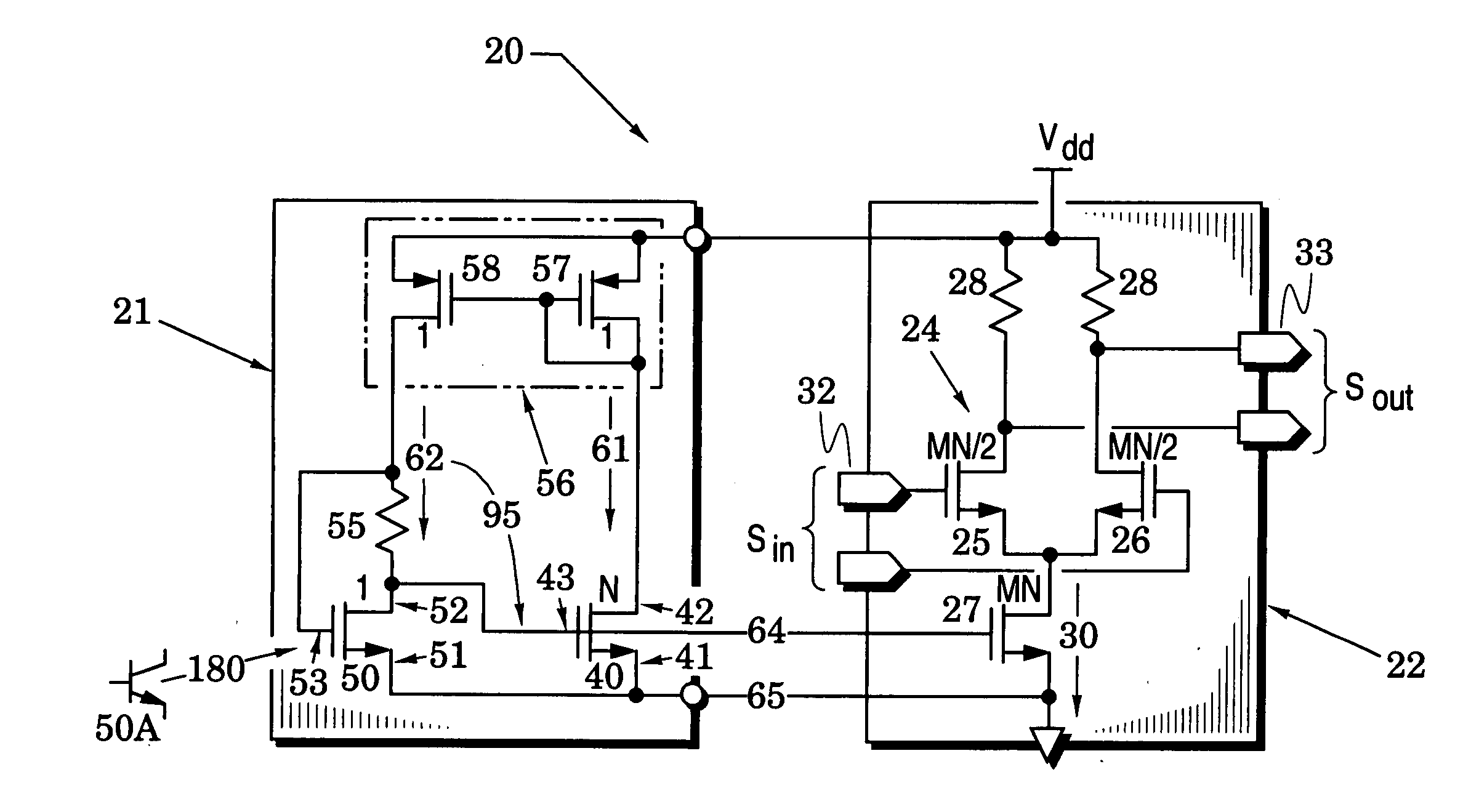
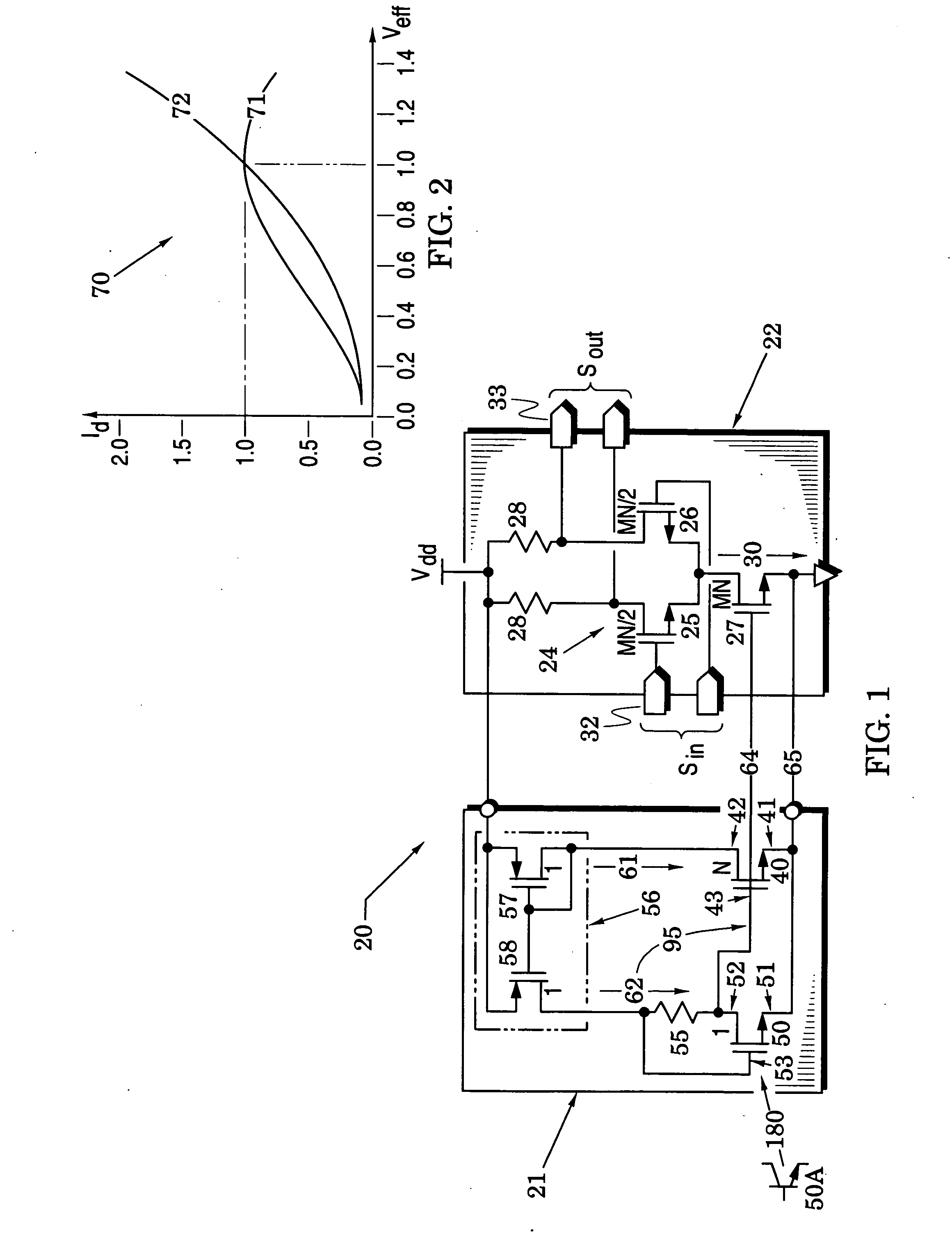
[0020] In particular, FIG. 1 illustrates an amplifier system embodiment 20 that comprises a bias generator 21 and a differential amplifier 22. The amplifier 22 has a differential pair 24 of transistors 25 and 26, a current-source transistor 27 and resistors 28. The differential pair 24 is coupled to receive a tail current 30 from the current-source transistor 27 and to differentially steer the tail current across the resistors 28 in response to a differential input signal Sin from an amplifier input port 32. Currents steered to the resistors 28 provide a corresponding output signal Sout at an amplifier output port 33.

embodiment 21

[0021] The bias generator embodiment 21 includes a bias transistor 40 that has first and second bias current terminals 41 and 42 that are responsive to a bias control terminal 43. It also includes a drive transistor 50 which has first and second drive current terminals 51 and 52 that are responsive to a drive control terminal 53. The bias generator 21 further includes a reference resistor 55 and a current mirror 56 which is formed with a diode-coupled transistor 57 and a current transistor 58 that is control-terminal coupled to the diode-coupled transistor 57.

[0022] In the embodiment of FIG. 1, the reference resistor 55 is coupled between the drive control terminal 53 and the second drive current terminal 52. The second drive current terminal 52 is then coupled to drive the bias control terminal 43. The current mirror 56 is arranged to mirror a first current 61 in the second bias terminal 42 to a second current 62 that is conducted through the reference resistor 55 to the second dri...

embodiment 100

[0052]FIG. 5 illustrates another amplifier system embodiment 100 which comprises a bias generator 101 and a complementary common-source amplifier 102. The amplifier 102 has transistors 103 and 104 with their control terminals (e.g., gates) coupled to receive an input signal Sin from an amplifier input port 105 and their second current terminals (e.g., drains) coupled to provide an output signal Sout at an amplifier output port 106. The first current terminal (e.g., source) of transistor 103 is coupled to ground and the first current terminal of transistor 104 is coupled through the low impedance (at a frequency of operation) of a capacitor 107 to ground.

[0053] The bias generator 101 includes a first drive transistor 50, a first reference resistor 55 that is coupled between a control terminal and a current terminal of the first drive transistor, a second drive transistor 120, and a second reference resistor 125 that is coupled between a control terminal and a current terminal of the ...


PUM


Abstract

Amplifier systems are provided with bias generators that substantially stabilize operating points of system parameters (e.g., drain current and transconductance) over PVT variations, substantially reduce body effects and Early effects, and substantially reduce system output noise. These advantages are realized without significantly increasing system size and / or power consumption.

Description

BACKGROUND OF THE INVENTION [0001] 1. Field of the invention [0002] The present invention relates generally to amplifier systems having bias signals provided by bias generators. [0003] 2. Description of the Related Art [0004] A significant number of bias generators have been proposed for providing bias signals that enhance and / or stabilize transistor amplifier parameters (e.g., amplifier current, transconductance, voltage gain, and noise) in the presence of process, voltage supply and temperature (PVT) variations. [0005] These generators have generally failed to effectively control at least one contributing source of error in amplifier performance. For example, several of these bias generators are configured so that an important metal-oxide-semiconductor (MOS) bias transistor has a body-to-source voltage VBS that differs from others of the bias transistors. This causes at least one bias transistor to exhibit a “body effect” which alters its threshold voltage VTH so that its drain cu...

Claims


Application Information

Patent Timeline
IPC IPC(8): H03F3/45
CPCH03F1/301H03F3/45183
Inventor KLEMMER, NIKOLAUS
Owner ANALOG DEVICES INC
Why Eureka
Try Eureka