Daisy chain cascading devices

a cascading device and chain technology, applied in the field of cascading devices of chain cascaded devices, can solve the problems of limiting the performance of these subsystems, adding to the complexity of boards that implement these subsystems, and limiting the number of devices incorporated in these subsystems, so as to reduce the complexity of implementation, reduce the footprint, and increase the speed

Inactive Publication Date: 2007-04-05
CONVERSANT INTPROP MANAGEMENT INC
View PDF99 Cites 161 Cited by
  • Summary
  • Abstract
  • Description
  • Claims
  • Application Information

AI Technical Summary

Benefits of technology

[0009] The techniques described herein overcome the above shortcomings by providing a technique for coupling devices in a serial daisy chain cascading arrangement that employs fewer and shorter connections than parallel interconnection implementations. Configuring devices in the daisy chain arrangement may allow the devices to be operated at higher speeds than parallel interconnection implementations because utilizing fewer and shorter interconnections makes the overall implementation less vulnerable to undesirable effects, such as propagation delay and crosstalk. Moreover, fewer and shorter connections tend to reduce the complexity of the implementation. This reduced complexity further enables a subsystem containing the devices to be implemented in a smaller area thus allowing the subsystem to occupy a smaller footprint.

Problems solved by technology

This adds to the complexity of boards that implement these subsystems.
Moreover, undesirable effects associated with large numbers of interconnections, such as crosstalk, tend to limit the performance of these subsystems.
In addition, the number of devices incorporated in these subsystems may be limited due to propagation delay of signals carried by the interconnections.
Moreover, fewer and shorter connections tend to reduce the complexity of the implementation.

Method used


Image

  • Daisy chain cascading devices
  • Daisy chain cascading devices
  • Daisy chain cascading devices

Examples


Embodiment Construction

[0030] A description of preferred embodiments of the invention follows.

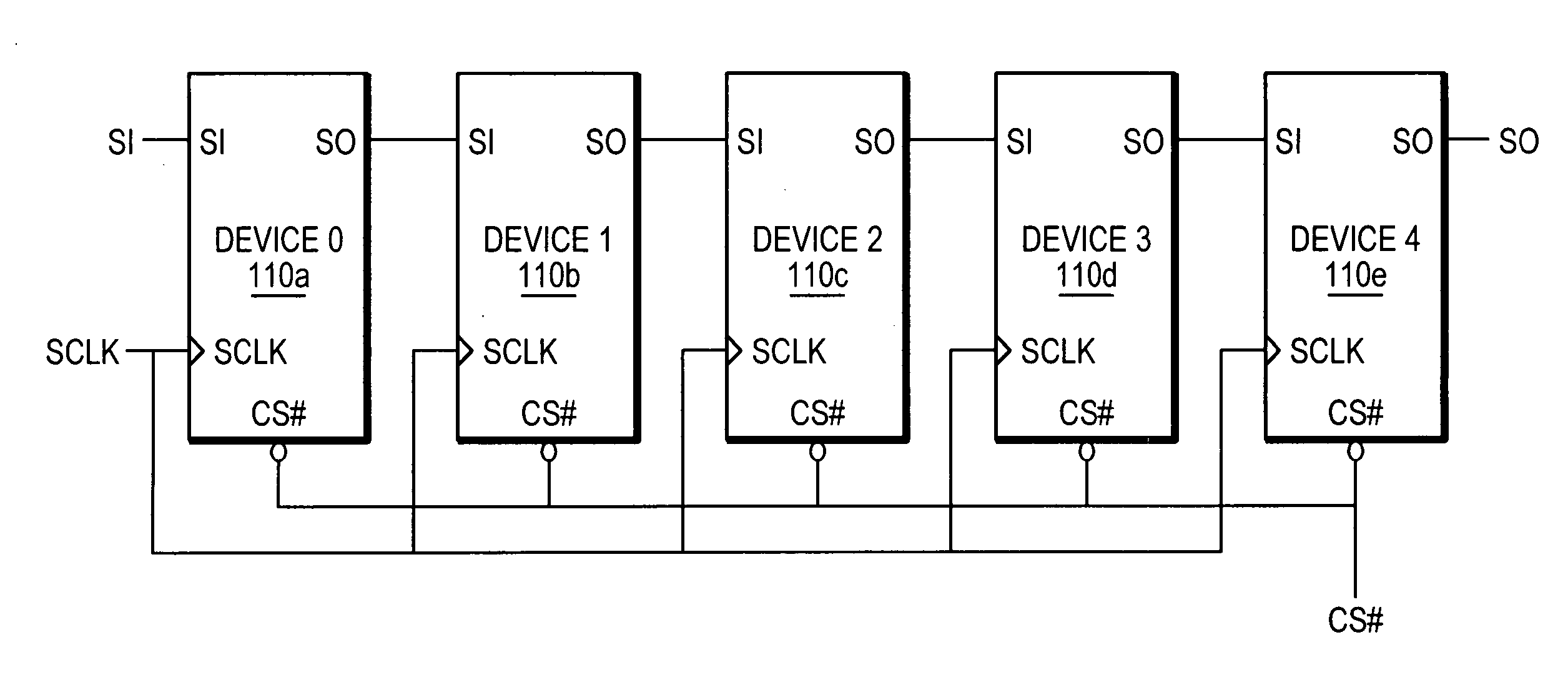
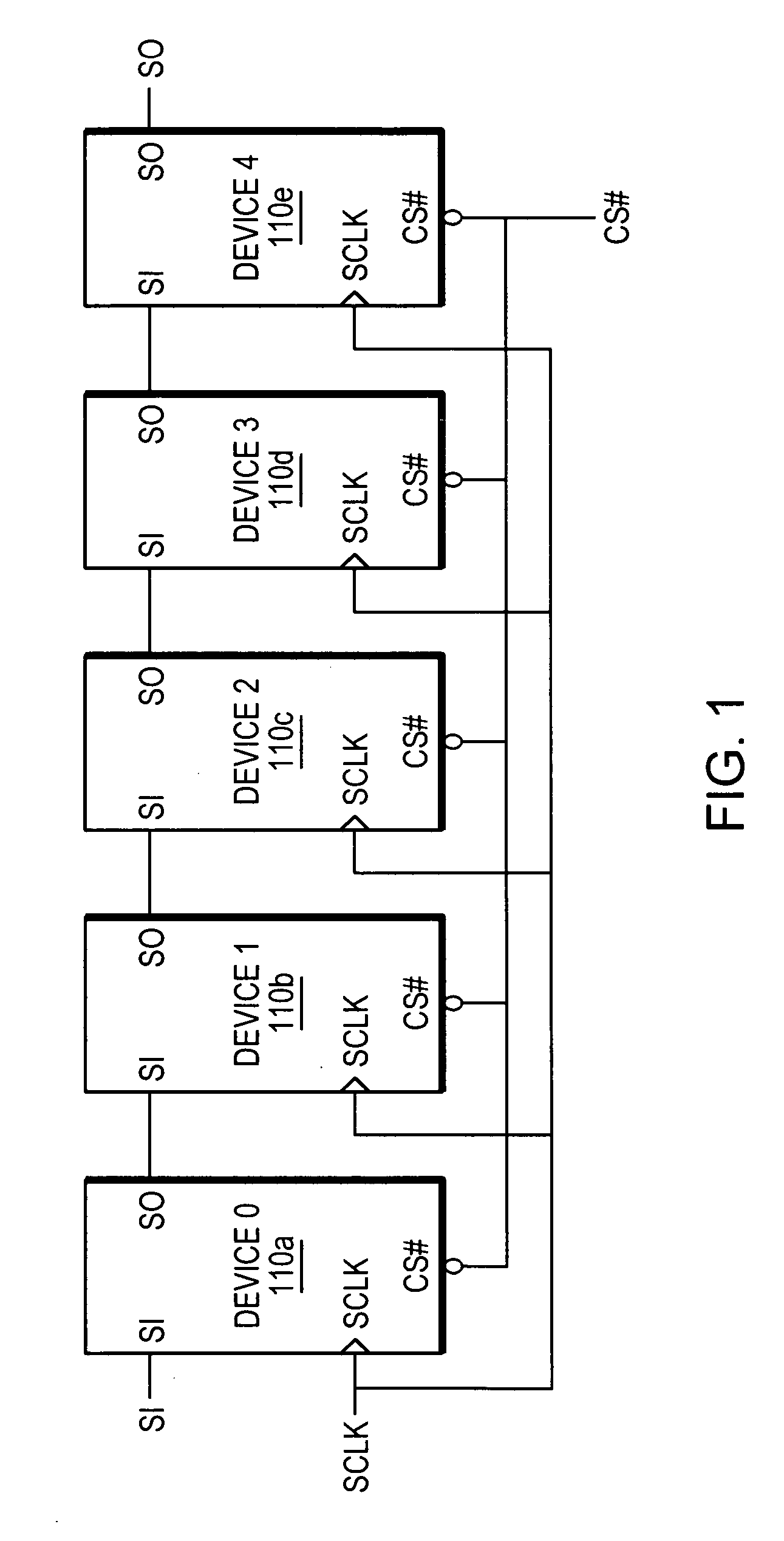
[0031]FIG. 1 is a block diagram of an exemplary device configuration comprising a plurality of single port devices 110a-e configured in a serial daisy chain cascade arrangement. The devices 110a-e are illustratively memory devices each of which contains a memory (not shown) which may comprise Dynamic Random Access Memory (DRAM) cells, Static Random Access Memory (SRAM) cells, flash memory cells and the like. Each device 110 comprises a serial input (SI), a serial output (SO), a clock (SCLK) input and a chip select (CS#) input.

[0032] The SI is used to transfer information (e.g., command, address and data information) into the device 110. The SO is used to transfer information from the device 110. The SCLK input is used to provide an external clock signal to the device 110 and the CS# input is used to provide a chip select signal to the device 110. An example of a device that may be used with the techniques descr...


PUM


Abstract

A technique for serially coupling devices in a daisy chain cascading arrangement. Devices are coupled in a daisy chain cascade arrangement such that outputs of a first device are coupled to inputs of a second device later in the daisy chain to accommodate the transfer of information, such as data, address and command information, and control signals to the second device from the first device. The devices coupled in the daisy chain comprise a serial input (SI) and a serial output (SO). Information is input to a device via the SI. The information is output from the device via the SO. The SO of an earlier device in the daisy chain cascade is coupled to the SI of a device later in the daisy chain cascade. Information input to the earlier device via the device's SI is passed through the device and output from the device via the device's SO. The information is then transferred to the later device's SI via the connection from the earlier device's SO and the later device's SI.

Description

RELATED APPLICATION(S) [0001] This application is a continuation in part of U.S. patent application Ser. No. 11 / 324,023 filed Dec. 30, 2005 which claims the benefit of U.S. Provisional Application No. 60 / 722,368, filed on Sep. 30, 2005 and this application claims the benefit of U.S. Provisional Application No. 60 / 787,710, filed on Mar. 28, 2006. The entire teachings of the above applications are incorporated herein by reference.BACKGROUND OF THE INVENTION [0002] Today computer-based systems can be found most everywhere and have made inroads into many devices that are used by society everyday, such as cell phones, handheld computers, automobiles, medical devices, personal computers and so on. In general, society has placed much reliance on computer-based systems to handle everyday tasks such as simple tasks like balancing checkbooks to relatively complex tasks such as predicting the weather. As technology improves, more and more tasks are migrated to computer-based systems. This, in ...

Claims


Application Information

Patent Timeline
Patent Type & Authority Applications(United States)
IPC IPC(8): G11C7/00
CPCG11C5/066G11C16/06G11C7/10G06F13/4247G06F13/4256G06F13/14G11C7/22G06F12/0623
Inventor PYEON, HONG BEOMKIM, JIN-KI
Owner CONVERSANT INTPROP MANAGEMENT INC
Why Eureka
Try Eureka