
Color filter, semi-transmissive semi-reflective liquid-crystal display device, method for forming phase difference control layer, and method for manufacturing color filter

a liquid crystal display device and semi-transmissive technology, applied in the field of color filters, can solve the problems of inability to reuse illumination light, inability to adapt to reduce the thickness of the device, and inability to reflect collected light, so as to prevent color leakage in the case of black display, uniform circular polarization state, and reduced wavelength dispersion

Inactive Publication Date: 2007-04-05
DAI NIPPON PRINTING CO LTD
View PDF8 Cites 34 Cited by
  • Summary
  • Abstract
  • Description
  • Claims
  • Application Information

AI Technical Summary

Benefits of technology

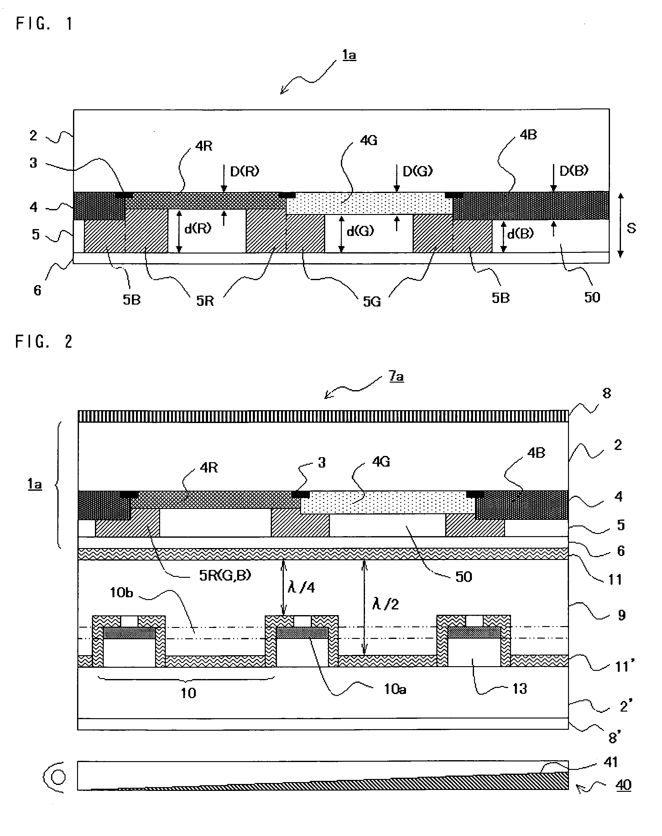
[0051] Because an optimum phase difference amount can thus be obtained with the color filter of the present invention according to a wavelength of the visible light passing through the color filter, wavelength dispersion can be reduced and a uniform circular polarization state can be formed over the entire visible light range.
[0052] Furthermore, with the semi-transmissive semi-reflective liquid-crystal display device in accordance with the present invention, color leak in the case of black display can be prevented and a high-grade display can be performed.

Problems solved by technology

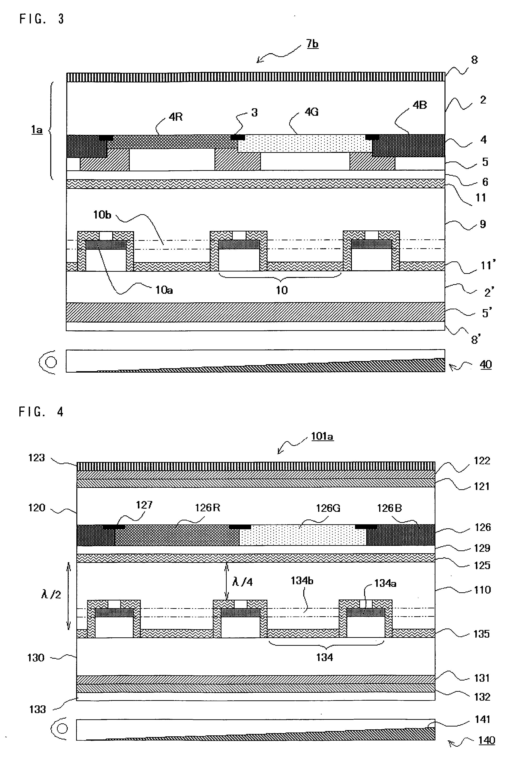
However, the drawback of the above-described conventional liquid-crystal display device 101a in which two phase difference plates are provided via adhesive layers between the upper and lower substrates 120, 130 and the polarization plates is that because the thickness of the entire device is rather large, such a configuration cannot be adapted to decrease the device thickness.
The resultant problem is that the collected light cannot be reflected again toward the liquid-crystal layer 110 by the backlight reflection plate 141 and the illumination light cannot be reused.
However, polymerizable liquid-crystal materials generally have a wavelength dispersion characteristic of a refractive index such that the refractive index anisotropy increases at a short wavelength, and when the films of the same thickness are produced from the same material, a good circularly polarized state cannot be formed over the entire wavelength range of visible light.
Therefore, in the red color region and blue color region, the phase difference amount is insufficient or excessive, and a perfect circular polarization cannot be obtained.
The resultant problem is that when black display is performed on a liquid-crystal screen, light components leak in those regions and a black display with a violet tint is obtained.

Method used


Image

  • Color filter, semi-transmissive semi-reflective liquid-crystal display device, method for forming phase difference control layer, and method for manufacturing color filter
  • Color filter, semi-transmissive semi-reflective liquid-crystal display device, method for forming phase difference control layer, and method for manufacturing color filter
  • Color filter, semi-transmissive semi-reflective liquid-crystal display device, method for forming phase difference control layer, and method for manufacturing color filter

Examples


example 1

(1) Configuration of Substrate and Color Layer

[0172] Photosensitive resin compositions (photoresists) for forming a black matrix and color pattern layers of the color layer that will be formed on the substrate was prepared. Each photoresist was prepared by mixing a dispersion and a resist composition. The dispersion was obtained by adding beads to a pigment, a dispersant and a solvent, using a paint shaker as a dispersing machine, dispersing for 3 h, and removing the beads. The resist composition comprises a polymer, a monomer, an additive, an initiator and a solvent. The composition of each photoresist is shown below. All the numbers are based on the weight standard. Photoresists for a total of six colors were prepared to configure the transmissive sections and reflective sections in RGB in order to match the spectral densities of the transmissive sections and reflective sections.

(i) Photoresist for black matrix formationBlack pigment (manufactured by Dainippon14.0partsSeika Ko...

example 2

[0187] In Example 2, a sample was used that was configured in the same manner as in Example 1, except that heating after ultraviolet exposure was conducted at a temperature of 200° C. and exposure in this state was conducted for 10 min with ultraviolet radiation (irradiation dose 10 J / cm2, wavelength 365 nm). The phase difference amount of the sample for each color is presented below.

Film thickness [μm] / Site:Phase difference [nm]Red color (610 nm) reflective section:1.62 / 155Green color (550 nm) reflective section:1.43 / 137Blue color (450 nm) reflective section:1.19 / 112

[0188] The sample of such configuration was subjected to an orientation film test under the same conditions as in Example 1. Both the film thickness and the phase difference almost maintained the initial values. The time necessary for curing was reduced apparently by additionally using ultraviolet radiation.


PUM


Abstract

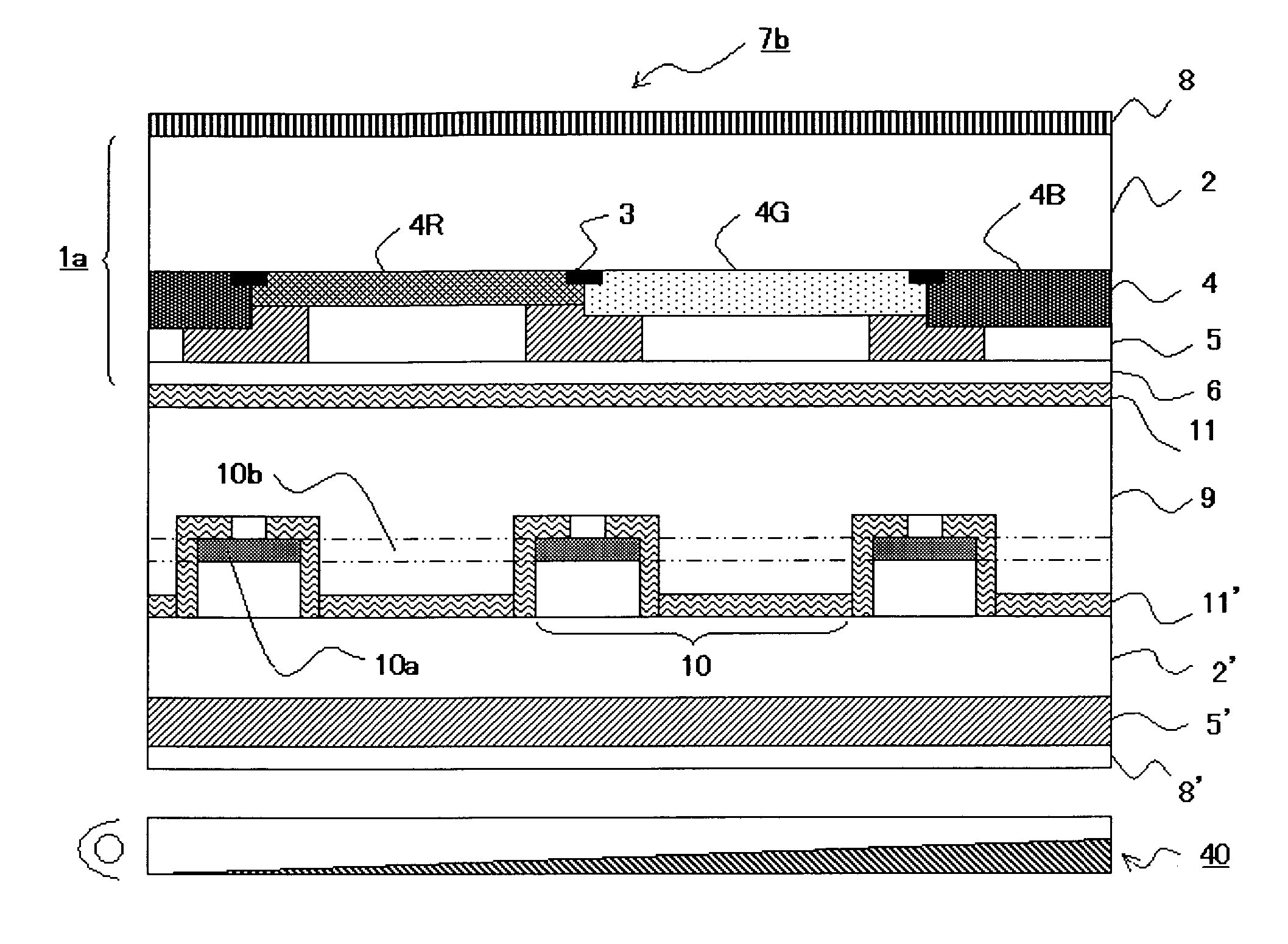
A color filter of the present invention comprises a substrate having light transmissivity, a color layer provided on the lower surface of the substrate and comprising a plurality of color pattern layers, each transmitting visible light of different color, and a phase difference control layer comprising a plurality of phase difference pattern layers and optically isotropic layers and provided on the lower surface of the color layer. A color differentiation region comprising a color pattern layer and a phase difference pattern layer and an optically isotropic layer that are provided on the lower surface of the color pattern layer is formed for each color of the color pattern layer, and the thickness of the phase difference pattern layer and the thickness of the color pattern layer are respectively different for each color differentiation region.

Description

BACKGROUND OF THE INVENTION [0001] 1. Field of the Invention [0002] The present invention relates to a color filter which can reduce wavelength dispersion and can form a good circular polarization state over the entire visible light range and to a semi-transmissive semi-reflective liquid-crystal display device using such color filter, and also to a method for forming a phase difference (retardation) control layer and a method for manufacturing a color filter. [0003] 2. Description of the Related Art [0004] A variety of liquid-crystal display devices have been developed, but according to a mode of using the light they can be generally classified into reflective liquid-crystal display devices that use an external light such as natural light or indoor light, transmissive liquid-crystal display devices that use an illumination light from a backlight, and semi-transmissive semi-reflective liquid-crystal display devices that can be both reflective and transmissive. [0005] A device of the ...

Claims


Application Information

Patent Timeline
IPC IPC(8): G02F1/1335
CPCG02F1/133371G02F1/133514G02F1/13363G02F2001/133565G02F2203/09G02F2413/02G02F2413/09G02F1/133565G02F1/133631
Inventor MORIYA, NORIHISA
Owner DAI NIPPON PRINTING CO LTD
Learn More