Wide range pressure control using turbo pump

Active Publication Date: 2007-04-12
EDWARDS VACUUM LLC
View PDF6 Cites 122 Cited by
  • Summary
  • Abstract
  • Description
  • Claims
  • Application Information

AI Technical Summary

Benefits of technology

[0031] Another embodiment of the invention is a method for exhausting gas from an exhaust port of a vacuum chamber and through a turbomolecular pump, to maintain a process pressure in the chamber. The method includes the steps of measuring a pressure in the vacuum chamber, regulating an opening size of a throttle valve in communicat

Problems solved by technology

That decreases the chances of contamination (e.g., in clean-surface studies and preparation of pure, thin films).
In that region the resolution of pressure control becomes limited, one step of the stepper motor results in a big shift in the conductance and control stability is thereby compromised.
In that region, however, a very small change in valve opening yields a very large change in flow rate, causing instability in the pressure control.
That limits the ability to control at higher pressures and lower flows when the valve is throttling a large turbomolecular pump with a large diameter inlet port.
The use of low pressure, high flow and high pressure, low flow steps in the same recipe also presents a significant stability problem for hardware engineers.
T

Method used


Image

  • Wide range pressure control using turbo pump
  • Wide range pressure control using turbo pump
  • Wide range pressure control using turbo pump

Examples


Example

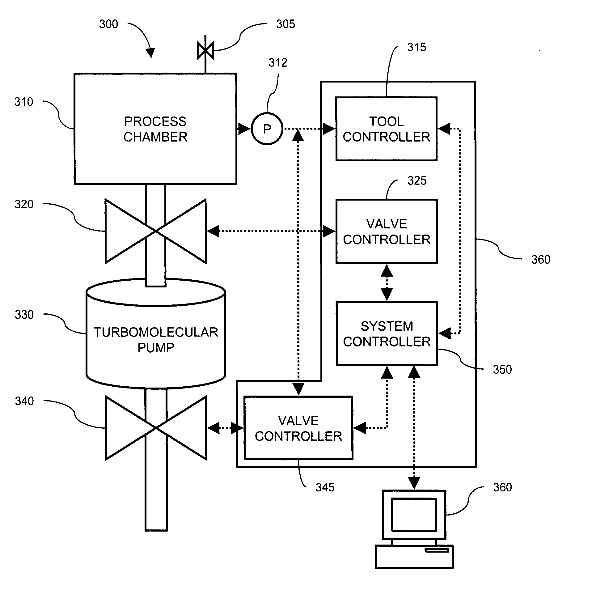
[0038] The present invention is a system and method for dynamically adjusting the effective pumping speed of a large turbomolecular pump that is used in combination with a throttling gate valve between the turbo pump and a process chamber. The system and method allow a wide range of stable pressure control.

[0039] The invention will be described with respect to one embodiment in which a process chamber for processing semiconductors is evacuated. One skilled in the art will recognize that the system may be used in other applications requiring high vacuum, such as research instruments.

[0040] The invention utilizes the compression properties of turbomolecular pumps to dynamically adjust the pumping speed at the inlet port of the pump. The compression ratio of a turbo pump is usually such that as the backing pressure changes, the inlet pressure remains constant. However, above a certain backing pressure (that is determined by the turbo pump rotor design) a change in the backing pressur...


PUM

PropertyMeasurementUnit
Pressureaaaaaaaaaa
Flow rateaaaaaaaaaa
Speedaaaaaaaaaa

Abstract

The present invention is an apparatus and method for controlling a process flow rate and a pressure in a vacuum process chamber that is evacuated by a turbomolecular pump. A throttle valve between the pump and the process chamber is controlled to regulate the pressure and flow rate. A backing valve downstream of the pump is also controlled to maintain the setting of the throttle valve within a preferred, stable operating range.

Description

FIELD OF THE INVENTION [0001] The present invention relates generally to the field of vacuum pumping, and more particularly, to a method and apparatus for providing and precisely controlling high vacuum at varying flow rates and pressures. BACKGROUND OF THE INVENTION [0002] Certain research and manufacturing processes require the use of a process chamber with high vacuum. The vacuum may be required for any of a number of reasons. In some instances, atmospheric components that could cause a chemical reaction or physical damage during a process must be removed (e.g., in vacuum melting of reactive metals such as titanium). In other instances, vacuum is used to disturb an equilibrium condition existing at normal room conditions, such as in removing volatile liquid or occluded or dissolved gas from the bulk of material (e.g., degassing oils, freeze-drying) or in desorbing gas from surfaces (e.g., the cleanup of microwave tubes during manufacture). Vacuum is also used in processes where t...

Claims


Application Information

Patent Timeline
IPC IPC(8): B32B27/04C23C16/00
CPCC23C16/4412F04D27/0253F04D19/042C23C16/45557F01C1/24F04D19/04H01L21/02
Inventor HOLLAND, PETER JOHNWILSON, KATESTEPHENSON, DAWN
Owner EDWARDS VACUUM LLC
Why Eureka
Try Eureka