Alternating current light-emitting device

a technology of alternating current and light-emitting device, which is applied in the direction of solid-state devices, electric lighting sources, electric light sources, etc., can solve the problems of shortened operating life and even high temperature-induced failure, waste of light-emitting area, and increased mass production difficulty

Active Publication Date: 2007-04-12
EPISTAR CORP
View PDF6 Cites 24 Cited by
  • Summary
  • Abstract
  • Description
  • Claims
  • Application Information

AI Technical Summary

Benefits of technology

[0013] A further objective of the present invention is to provide an alternating current light-emitting device that can emit light evenly.

Problems solved by technology

In addition to the necessity of paying royalties, drawbacks of the patented Nichia process include the distribution ratio of fluorescent powder and the relatively high color temperature of white light arising from a coverage process that leads to shortened operating life and even high temperature-induced failure.
Moreover, the prior art fails to provide good packaging control, making mass production more difficult.
In other words, at every single moment, a light-emitting area merely accounts for a half of the surface area of a chip, while the micro-dies associated with another half of the surface area of the chip are in an off state, resulting in a waste of the light-emitting area.
Further, a micro-die disclosed by the aforesaid patent has an isosceles, right-angle triangular shape with two legs approximately a mere 70 micrometers long each, causing difficulty in the fabrication process where it is necessary to reduce the size of the LEDs in order to meet the need for product miniaturization.
Furthermore, since the aforesaid patent involves the use of patented Nichia fluorescent powder, the foregoing drawbacks of high color temperature and a hard-to-control packaging process still exist.

Method used


Image

  • Alternating current light-emitting device
  • Alternating current light-emitting device
  • Alternating current light-emitting device

Examples


Embodiment Construction

[0036] The present invention discloses an alternating current light-emitting device applicable to a chip. In the presence of an applied alternating current (AC), the disclosed alternating current light-emitting device is capable of emitting monochromatic light, white light, or colored light to meet user needs. The monochromatic light or colored light is emitted as a result of all-time light emission occurring to a light-emitting surface of the chip. The preferred embodiment is achieved by general electric supply according to the universal electricity standards, under a voltage of 110V, 110V or 220V, at a frequency of 60 Hz or 50 Hz.

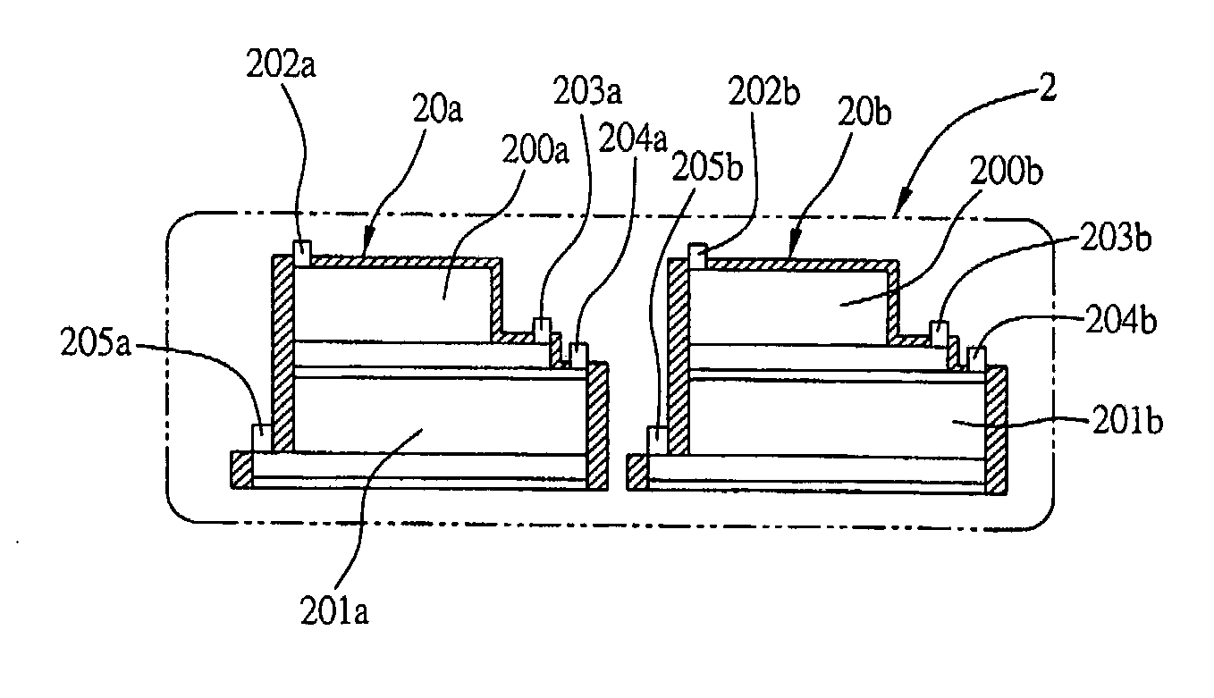
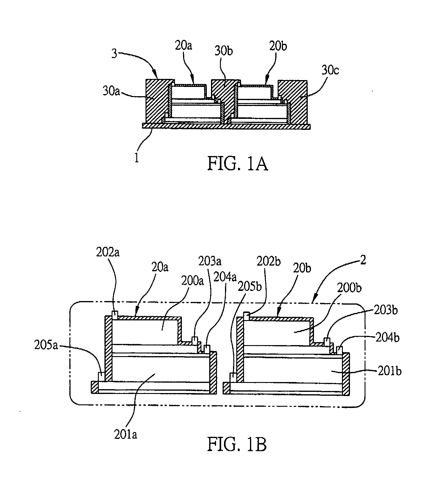
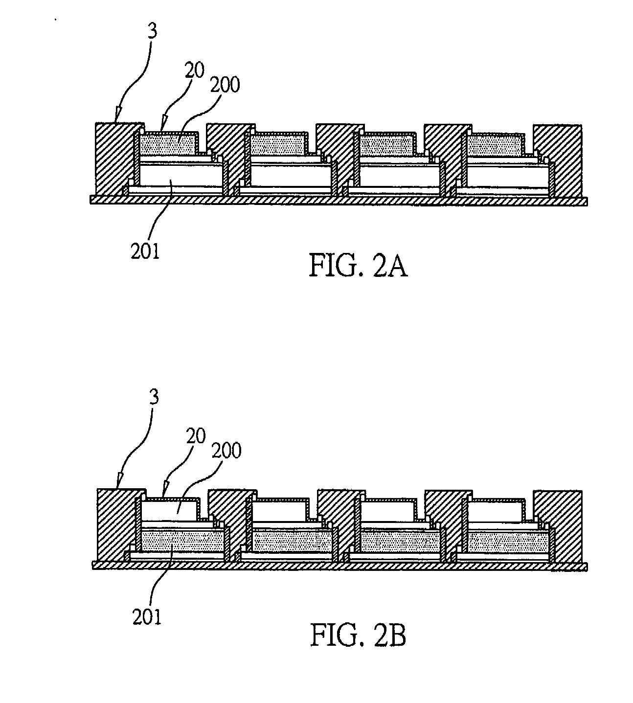
[0037]FIGS. 1A and 1B each shows a cross-sectional view of the structure of the alternating current light-emitting device of the present invention. The drawings depict only a single alternating current light-emitting device in this preferred embodiment. The alternating current light-emitting device comprises a substrate 1, an alternating current micro-di...


PUM


Abstract

An alternating current light-emitting device and the fabrication method thereof is disclosed. The alternating current light-emitting device includes at least one alternating current micro-die light-emitting module formed on a substrate and composed of at least two micro-dies connected to one another. The micro-dies, each includes at least two active layers, are electrically connected by a conductive structure, such that the active layers of the micro-dies take turns emitting light during positive and negative half cycles of alternating current, thereby providing a full-scale light-emitting area for all-time light emission.

Description

BACKGROUND OF THE INVENTION [0001] 1. Field of the Invention [0002] The present invention relates to a light-emitting device, and more particularly, to an alternating current light emitting device and the fabrication method thereof. [0003] 2. Description of Related Art [0004] Unlike the light emission principle of white light, the light emission principle of light emitting diodes (LEDs) involves applying electric current to light-emitting materials so as to produce light. Hence, LEDs are also known as cold light sources. LEDs have their own advantages, namely highly durable, longevity, light and compact, low power consumption, absence of harmful substances such as mercury, and so forth, thus the development of LED-based solid state lighting has become one of the crucial research targets for the global lighting industry as well as the semiconductor industry. Common applications of LEDs include white light illumination, indicator lights, vehicle signal and illuminating lights, flash l...

Claims


Application Information

Patent Timeline
Patent Type & Authority Applications(United States)
IPC IPC(8): H01L33/00H01L33/08H01L33/20H01L33/32
CPCH01L25/0753H05B33/0803H05B33/0821H01L2924/0002H01L2924/00H05B45/40H05B45/00H05B45/30
Inventor LIN, MING-TEYEN, HSI-HSUANYEH, WEN-YUNGLIN, MING-YAOHUANG, SHENG-PAN
Owner EPISTAR CORP
Why Eureka
Try Eureka