Polarization-modulating optical element

a technology of optical elements and modulators, applied in the field of optical elements, can solve the problems of high production costs and significant detrimental effects on the imaging process

Inactive Publication Date: 2007-04-12
CARL ZEISS SMT GMBH
View PDF98 Cites 82 Cited by
  • Summary
  • Abstract
  • Description
  • Claims
  • Application Information

AI Technical Summary

Benefits of technology

[0009] The present invention therefore has the objective to propose a polarization-modulating optical element which—with a minimum loss of intensity—affects the polarization of light rays in such a way that from linearly polarized light with a first distribution of the directions of the oscillation planes of individual light rays, the optical element generates linearly polarized light with a second distribution of the directions of the oscillation planes of individual light rays.

Problems solved by technology

The different degrees of reflection and refraction that occur in the s-component in comparison to the p-component have a significant detrimental effect on the imaging process.
However, because the raster arrangement is produced by joining a large number of individually oriented half-wave plates, it is expensive to produce.

Method used


Image

  • Polarization-modulating optical element
  • Polarization-modulating optical element
  • Polarization-modulating optical element

Examples


Embodiment Construction

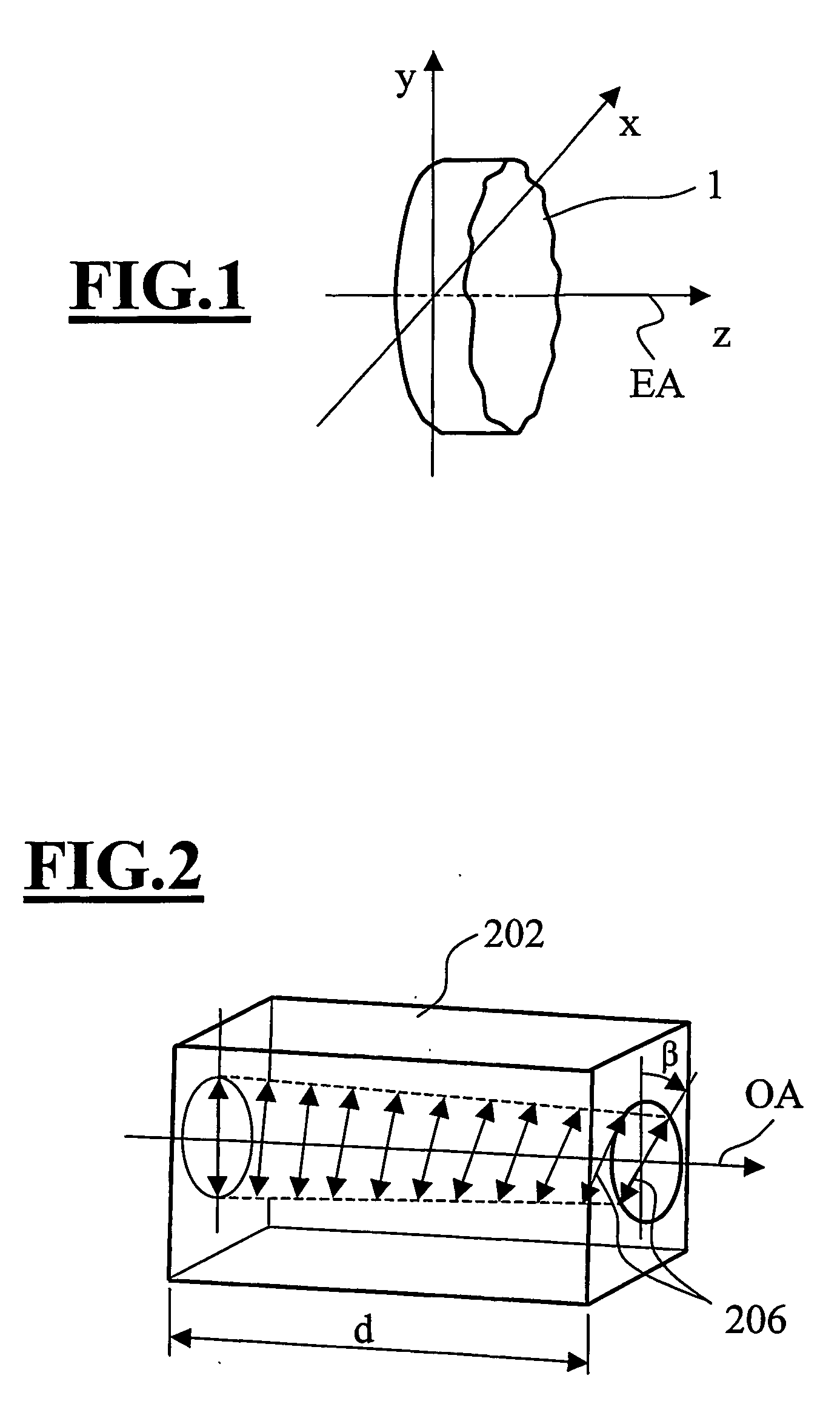
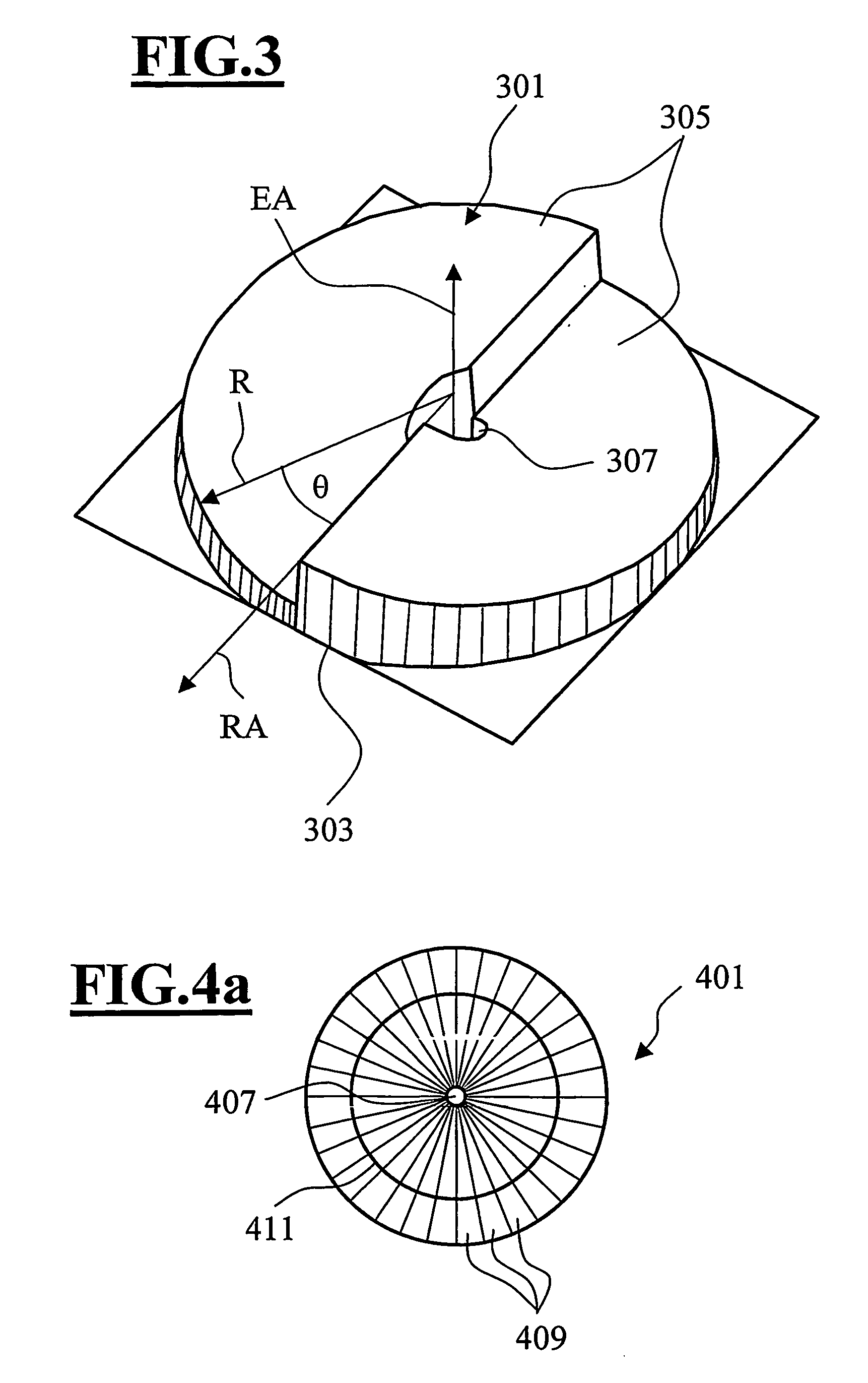
[0058]FIG. 1 illustrates a polarization-modulating optical element 1 of an optically active material. Particularly well suited for this purpose are optically active crystals with at least one optical crystal axis which are transparent for the wavelength of the light being used. For example TeO2 works in a range of wavelengths from 1000 nm down to 300 nm, AgGaS2 works from 500 nm to 480 nm, and quartz from 800 nm down to 193 nm. The polarization-modulating optical element 1 is designed so that the element axis is oriented parallel to the optical crystal axis. In order to produce a selected polarization distribution, the optical element 1 is designed with a thickness profile (measured parallel to the element axis EA) which varies in the directions perpendicular to the element axis EA, also comprising variations in thickness of the optical element in an azimuth direction θ (see FIG. 3) at e.g. a fixed distance of the element axis EA.

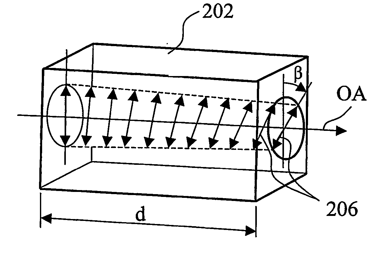
[0059]FIG. 2 will serve to explain the function of o...


PUM

PropertyMeasurementUnit
azimuth angleaaaaaaaaaa
azimuth anglesaaaaaaaaaa
angle of incidenceaaaaaaaaaa

Abstract

A polarization-modulating optical element (1) consisting of an optically active crystal material has a thickness profile where the thickness, as measured in the direction of the optical axis, varies over the area of the optical element. The polarization-modulating optical element (1) has the effect that the plane of oscillation of a first linearly polarized light ray and the plane of oscillation of a second linearly polarized light ray are rotated, respectively, by a first angle of rotation and a second angle of rotation, with the first angle of rotation and the second angle of rotation being different from each other.

Description

BACKGROUND OF THE INVENTION [0001] The invention relates to an optical element that affects the polarization of light rays. The optical element has a thickness profile and consists or comprises of an optically active crystal with an optical axis. [0002] In the continuing effort to achieve structures of finer resolution in the field of microlithography, there is a parallel pursuit of substantially three guiding concepts. The first of these is to provide projection objectives of very high numerical aperture. Second is the constant trend towards shorter wavelengths, for example 248 nm, 193 nm, or 157 nm. Finally, there is the concept of increasing the achievable resolution by introducing an immersion medium of a high refractive index into the space between the last optical element of the projection objective and the light-sensitive substrate. The latter technique is referred to as immersion lithography. [0003] In an optical system that is illuminated with light of a defined polarizatio...

Claims


Application Information

Patent Timeline
Patent Type & Authority Applications(United States)
IPC IPC(8): G02F1/1335G02B1/08G02B5/30G02B27/28G02F1/01G03F7/20
CPCG02B1/08G02B5/3025G02B5/3075G02B27/286G02F1/0136G02F1/0147G03F7/70341G03F7/70566G02B5/3083G03F7/70058
Inventor FIOLKA, DAMIANDEGUENTHER, MARKUS
Owner CARL ZEISS SMT GMBH
Why Eureka
Try Eureka