Apparatus for endpoint detection during polishing

a technology of endpoint detection and polishing, which is applied in the direction of grinding machine components, manufacturing tools, lapping machines, etc., can solve the problems of wafer over-polishing, increasing the complexity of microstructured components, and requiring higher inspection precision and better accuracy of each manufacturing process, so as to improve detection accuracy

Inactive Publication Date: 2007-04-12
IND TECH RES INST
View PDF15 Cites 13 Cited by
  • Summary
  • Abstract
  • Description
  • Claims
  • Application Information

AI Technical Summary

Benefits of technology

[0012] It is the primary object of the present invention to provide an apparatus of endpoint detection during polishing, which comprises at least a sensing element, capable of sensing the thickness variation an d planarity of a workpiece during a polishing process while it is being driven to proceed a linear motion of displacement, whereas each sensing element can be a device selected from the group consisting of an optical sensor, an eddy current sensor and the combination of the two, so that the apparatus of endpoint detection of the invention not only is advantaged in its all-zone detection ability, but also it has enhanced detection accuracy with respect to different metal layer of different thickness.

Problems solved by technology

It is known that miniaturization is the strategy to success, which requires small, high performance, versatile, highly reliable and inexpensive microstructured components, the structure of microstructured component has becoming more and more complex.
That is, the demanding for higher inspection precision and better accuracy of each manufacturing process are required.
(2) The EPDs used in the prior methods are all being fixed to a specific position that the area of detection on a large-sized wafer are limited and thus they can only be used as local detectors so that the accuracy of detection acquired thereby is not preferred since the overall thickness variation of the large-sized wafer can not be detected and measured by a local EPD.
It is noted that the planarity of the device surface seen in FIG. 2B is not ideal enough for the next processing step to be performed thereon, so that a polishing process is required to create a surface of enough planarity of flatness as seen in FIG. 2C.
However, since the prior-art EPD can only detect a portion of the substrate wafer while it is being used for determining the endpoint of a polishing process, a portion of the wafer might be over-polished while another portion thereof might be under-polished such that the thickness of the target layer is not uniform.
Furthermore, It is known that all the prior-art polishing processes are dependent on the calculation of total thickness variation (TTV) which used a designated base level as reference level that can cause error while the planarity of a workpiece is not sufficient or the workpiece is not being positioned properly.

Method used


Image

  • Apparatus for endpoint detection during polishing
  • Apparatus for endpoint detection during polishing
  • Apparatus for endpoint detection during polishing

Examples


first embodiment

[0033] The configuration of the sensing element 31 are selected basing on actual detection requirement, which can be an optical sensor 311, an eddy current sensor 312, or the combination of the two, as shown in FIG. 4, or other sensing devices. As the first preferred embodiment shown in FIG. 4, the sensing element is the combination of the optic sensor 311 and the eddy current sensor 312 so as to enhance the accuracy and quality of the detection since the workpiece is made of metallic material. That is, any sensor suitable for detection polishing status of a workpiece can be used as the sensing element.

[0034] The linear motion of displacement 91 is realized by a linear moving mechanism, such as a linear rail 32 shown in FIG. 4. The sensing element 31 is being disposed on a linear rail 32 while the linear rail 32 is arranged in the probe 30 such that the sensing element 31 can be driven to proceed a linear motion of displacement 91 along the linear rail 32 while enabling the same to ...

second embodiment

[0035] Please refer to FIG. 5, which is a schematic diagram of a second preferred embodiment according to the present invention. As seen in FIG. 5, there are a plurality of sensing elements 61 being arranged on the probe 60 of the endpoint detection apparatus 6, and the plural sensing elements 61 are being separated from each other by a specific interval while each is capable of being driven to proceed a linear motion of displacement 91 along a linear rail 64 arranged on the probe 60. the invention shown in FIG. 5, which allows a larger detection range, is suitable to be used for detecting a large-sized workpiece since the displacement of each sensing element 61 is small and thus the accuracy of detection inversely affected thereby is reduced.

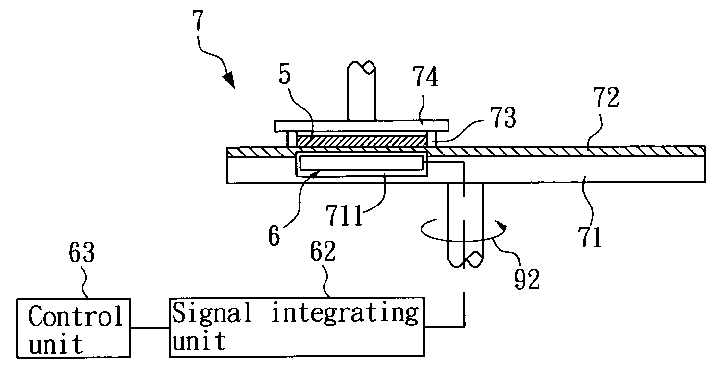
[0036] Please refer to FIG. 6, which is a schematic diagram showing the assembly of a polishing device and an endpoint detection apparatus of the invention. The polishing device 7, which can be a mechanical polishing device but is not limited t...


PUM


Abstract

An apparatus for endpoint detection during polish, being used to monitor the surface polishing status of a polishing surface of a workpiece, is disclosed, which comprises: a probe, being positioned above the workpiece by a height; and at least a sensing element, being disposed on the probe at a position corresponding to the polishing surface, capable of sensing the thickness variation of the workpiece during a polishing process as it is performing a surface dynamic scan upon the workpiece in rotating while it is being driven to proceed a linear motion of displacement. Preferably, the sensing element can be a device selected from the group consisting of an optical sensor, an eddy current sensor and the combination of the two for carrying out optical detection and magnetic flux detection. It is noted that the apparatus for endpoint detection of the invention not only is advantaged in its all-zone detection ability, but also it has enhanced detection accuracy with respect to different metal layer of different thickness.

Description

FIELD OF THE INVENTION [0001] The present invention relates to an apparatus capable of monitoring the thickness of a workpiece, and more particularly, to an apparatus having a sensing element disposed on a probe thereof while enabling the sensing element to perform a linear movement, which is capable of monitoring and measuring the surface polishing status of a workpiece during a polishing process. BACKGROUND OF THE INVENTION [0002] It is known that miniaturization is the strategy to success, which requires small, high performance, versatile, highly reliable and inexpensive microstructured components, the structure of microstructured component has becoming more and more complex. As manufacturers reduce the size of integrated circuit (IC) components to fit more components on each IC chip and as the substrate of IC manufacturing is getting larger, there is more going on in the IC fabrication process itself than a simple reduction in scale. That is, the demanding for higher inspection ...

Claims


Application Information

Patent Timeline
Patent Type & Authority Applications(United States)
IPC IPC(8): B24B49/00
CPCB24B37/013B24B49/10B24B49/12
Inventor GWO, TSUNG-JUCHANG, MING-WEIYANG, CHUNG
Owner IND TECH RES INST
Why Eureka
Try Eureka