
Tooth and adaptor assembly for a dipper bucket

a technology of adaptor and dipper bucket, which is applied in the direction of soil shifting machines/dredgers, constructions, etc., can solve the problems of reducing the use time-consuming installation and removal of the locking pin, and directional stresses and shock loads at exceedingly high levels, so as to reduce the possibility of tooth and/or adaptor nose breakage, reduce the possibility of shock and bearing loads, and improve the use

Inactive Publication Date: 2007-04-19
AMSCO CAST PRODS CANADA
View PDF30 Cites 22 Cited by
  • Summary
  • Abstract
  • Description
  • Claims
  • Application Information

AI Technical Summary

Benefits of technology

[0015] In one embodiment, the present invention utilizes an offset, substantially vertical retainer pin whereby installation and removal of the retainer pin is performed from the top surface of the tooth. There is no bottom through-hole necessary in the bottom of the tooth to “drift” the retainer pin out in order to disassemble the tooth from the adaptor. This design prevents entry of highly pressurized compaction forces from beneath that can force the typical base exposed retainer pin(s) upward and out of their latched position.
[0016] In another embodiment, the present invention provides an enclosed assembly comprising three components including a tooth, an adaptor and a retainer pin. The components are configured in such a way that the mated surfaces of the assembled components minimize debris from entering certain areas of the coupled and latched tooth and adaptor assembly. In another representative embodiment, the retainer pin has an enlarged head with a bottom surface having a beveled seating collar completely around and beneath the head. The head is adapted to cover the entirety of the retainer pin opening and to mate with the tooth top surface so as to prevent debris from entering the passageway. The head of the retainer pin does have some exposure to falling excavated debris that can assist in maintaining the retainer pin in its “home” latched position.
[0017] In another representative embodiment, the adaptor front portion has a rectangular front end and enlarges in cross-section towards the substantially circular base of the intermediate portion. The intermediate portion incorporates a ¾ round cylindrical shank having a flat side surface containing the groove, which is formed thereon. The front and intermediate portions are adapted to conform to an interior configuration of the tooth socket so as to prevent the tooth from rotating on the adaptor in the coupled position. Accordingly, the tooth remains stable on the adaptor while the maintenance worker is performing the tooth change-out. The possibility of the unlatched tooth sliding off the adaptor is virtually eliminated and this makes for safer working conditions.
[0018] In view of the complementary shapes of the front and intermediate portions of the adaptor and the tooth socket, the shock and bearing loads are more effectively distributed throughout the assembly. The front and intermediate portions form multi-directional load-bearing surfaces so as to reduce the possibility of tooth and / or adaptor nose breakage. The cylindrical shank also complements the overall load carrying capabilities of the assembly and the physical mass of the shank more than compensates for the loss of structural material given up to the groove that forms the passageway for the retainer pin.
[0019] The tooth and adaptor assembly of the present invention provides additional thrust-load bearing capacity with respect to forward directional movement of the assembly mounted on the excavation bucket and / or equipment. In particular, the present invention minimizes the amount of displacement that can occur between the tooth and the adaptor thereby reducing undesirable movement of the retainer pin within the passageway.
[0020] It is an object of the present invention to provide a tooth and adaptor assembly for a dipper bucket that is easily serviced. The tooth and adaptor assembly may be disassembled and reassembled with ease, without the need for excessive force applied by sledgehammers or the like. The retainer pin may be moderately tapped into the passageway formed when the tooth is fully seated on the adaptor to the “home” latched position with an ordinary machine hammer. A typical pry bar, or a similar tool, can easily remove the retainer lock-pin from its “home” latched position. One of the advantages of the retainer pin of the present invention is that it is not dependent on an elastomeric material to supports its primary function of keeping latched and maintaining the coupled position of the tooth on the adaptor. Accordingly, the retainer pin may be reused over the course of several tooth change outs, if necessary.

Problems solved by technology

Abrasive grinding, multi-directional stresses and shock loading at exceedingly high levels can continuously and abruptly assault the integrity of the tooth and adaptor assembly during any given excavation application.
Although the prior art disclosing the first generation elliptical tooth and adaptor system was functional, this system required certain installation and removal techniques that reduced its use in the field.
Installation and removal of the locking pin was also time consuming and physically difficult, particularly if the head of the pin became flattened (mushroom shaped) from repeated hammer blows.
This original design is no longer acceptable to maintenance workers in certain mining applications.
Deterioration of the elastomeric material was a common occurrence and the structural design of this tooth and adaptor system restricted the possibility of establishing a preferred locking system not so depended on this component.
Extreme flowing pressures (several tons) of excavated materials beneath the shovel bucket tended to force the original style of lock pin upward and out of the locked position.
Occasionally, these pins would actually be forced completely out and the tooth would fall off.
The loss of structural mass in the tooth sidewalls weakened this component, and occasionally, the tooth would break when subjected to severe digging applications.
If a maintenance worker unintentionally bumped an unlocked tooth, it could easily slide off, resulting in an injury to the worker.
This condition can leave the mating fit surfaces of the assembly, the lock pin bearing support surfaces and its related structural members vulnerable to the extreme flowing pressures (several tons) of excavated materials that are readily forced into these gaps.
The abrasive qualities of the ore, combined with any movement between the assembled components during the excavation process create an aggressive grinding effect that deteriorates these important dimensional load-bearing surfaces.
The resulting wear can contribute to a “loose fit” condition affecting all three assembled components.
If the retainer lock pin does become loose and falls out, the tooth and adaptor can uncouple, leaving the less wear-resistant adaptor male mating nose exposed to harsh wear from the continuing excavation process.

Method used


Image

  • Tooth and adaptor assembly for a dipper bucket
  • Tooth and adaptor assembly for a dipper bucket
  • Tooth and adaptor assembly for a dipper bucket

Examples


Embodiment Construction

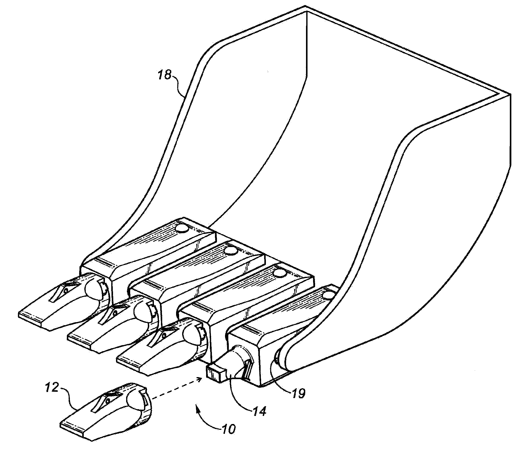
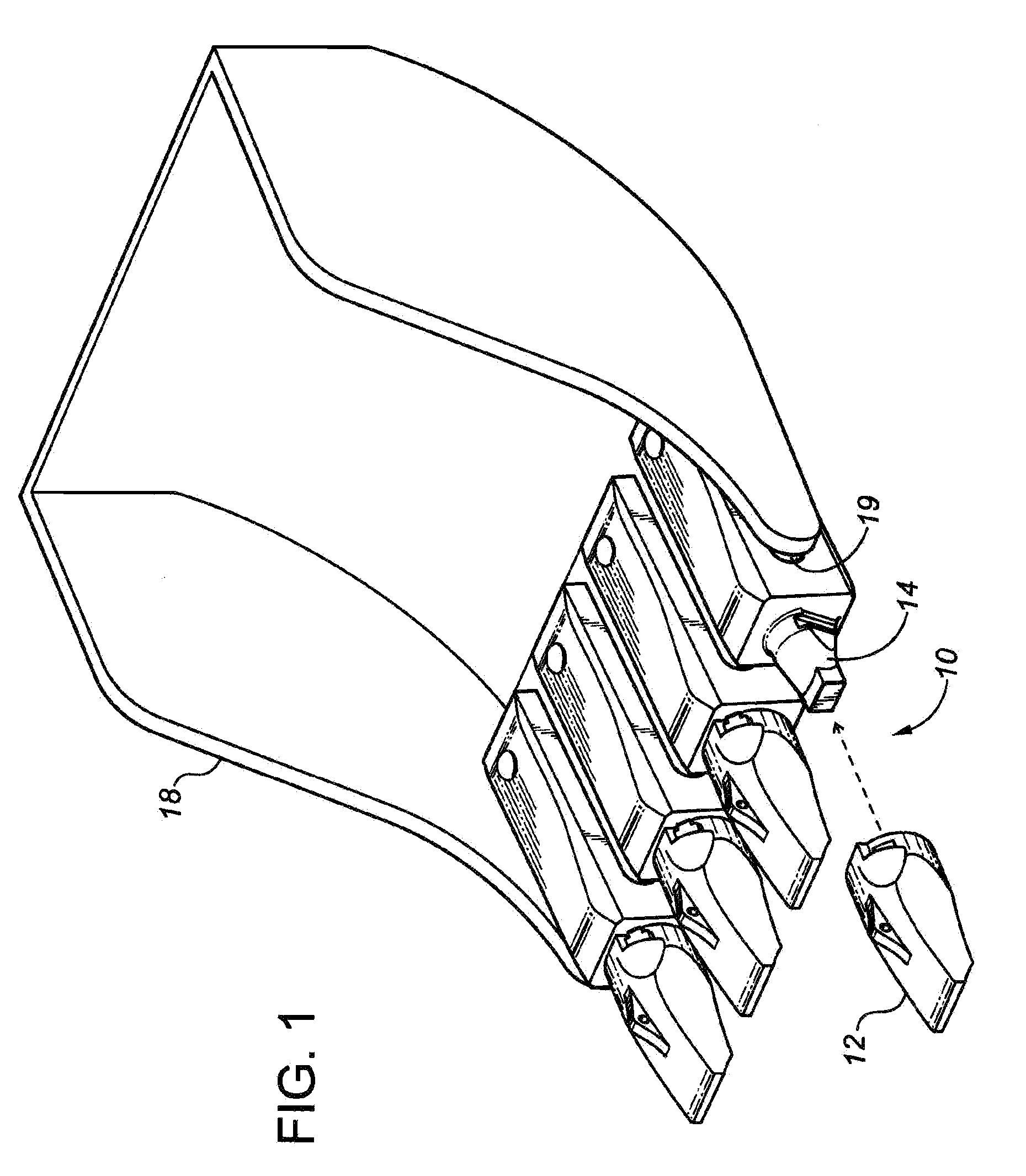
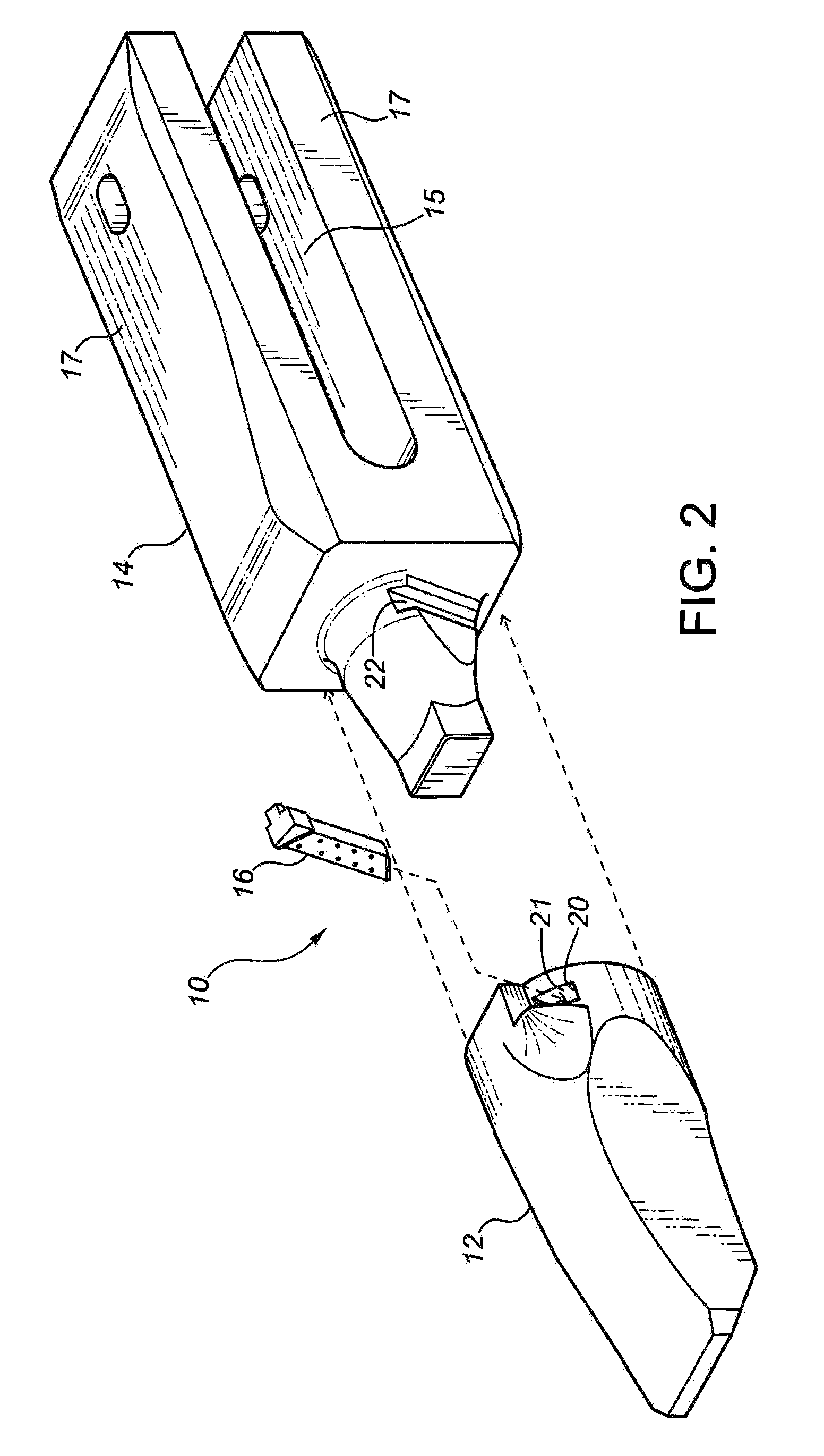
[0038] Referring to FIGS. 1 and 2, a representative embodiment of the present invention is shown. Tooth / adaptor assembly 10 broadly consists of excavation tooth 12, adaptor 14 and retainer pin 16. Adaptor 14 comprises an elongated U-shaped member that attaches to dipper bucket 18 on bucket lip 19 as well known to those skilled in the art. Tooth 12 is seated onto adaptor 14 and secured by retainer pin 16 that is inserted through opening 20 to fit snugly into groove 22. Tooth 12 is designed to bear the brunt of the wearing forces caused by excavating and will wear out over time. As tooth 12 wears out to the point that it is no longer serviceable, tooth 12 can be removed from adaptor 14 by extracting retainer pin 16 from opening 20 and sliding tooth 12 off of adaptor 14 so that a new tooth 12 may be installed.

[0039] Referring to FIGS. 3 and 4, side and top views of assembly 10 is shown with tooth 12 fully seated on adaptor 14. Tooth 12 has a pointed top 24 designed for excavating is s...


PUM


Abstract

A tooth and adaptor assembly is provided for a dipper bucket. The assembly includes an adaptor having a rear portion for attaching to a dipper bucket, a tooth capable of releasable attachment to the adaptor and a retainer pin for securing the tooth to the adaptor. The adaptor has a tapered intermediate portion that narrows to a rectangular front portion and a planar surface on a portion of its intermediate portion. A groove traverses the planar surface, and extends perpendicular to the horizontal longitudinal axis of the adaptor. The tooth has a tip at its front end for digging and a socket at its rear end that is configured to receive the front and intermediate portions of the adaptor. When the tooth is coupled to the adaptor, an opening on the rear end of the tooth aligns with the groove to define a passageway that terminates within the socket of the tooth. The retainer pin is inserted into the passageway to secure the tooth to the adaptor and complete the assembly.

Description

FIELD OF THE INVENTION [0001] The present invention relates to excavating equipment, and more particularly to an adaptor and tooth assembly for a dipper bucket. BACKGROUND OF THE INVENTION [0002] Excavation practice in construction and mining applications is often most efficiently carried out when ground engaging, penetration attachments (tooth and adaptor assemblies) are securely mounted on the leading digging edge of the excavation dipper bucket and / or excavation equipment. Usually, the adaptor(s) are rigidly attached by either welding or some form of mechanical fastener(s). [0003] This chisel-like assembly reduces the initial contact mass of the bucket edge moving into the material(s) being excavated by focusing the accumulated digging forces at the leading tooth point(s); thereby, maximizing the penetration efficiency of the excavating equipment. The loosened material(s) can then be freely loaded into the excavation bucket or diverted around the assembly when only break-up excav...

Claims


Application Information

Patent Timeline
Patent Type & Authority Applications(United States)
IPC IPC(8): E02F9/28
CPCE02F9/2825E02F9/2833E02F9/2841
Inventor BENTLEY, NEIL DOUGLAS
Owner AMSCO CAST PRODS CANADA
Learn More