Rotatable liquid reservoir for computer cooling

Inactive Publication Date: 2007-04-19
IBM CORP
View PDF9 Cites 6 Cited by
  • Summary
  • Abstract
  • Description
  • Claims
  • Application Information

AI Technical Summary

Benefits of technology

[0017] The invention has several objects, including (among others): eliminating any bubbles that enter the tank of a liquid cooling system for cooling electronic gear; not entraining additional bubbles into the liquid flow, especially through vortices formed near the outlet of the tank; avoiding cavitation; and operation of the system at any angle of orientation.
[0022] The invention can provide for a gradual increase in the cross-sectional area perpendicular to the flow, by choosing the diameters of the conduits correctly, by making them conical or otherwise divergent in shape, and by including perforations.

Problems solved by technology

When chips are ganged and collected in complex devices, the amount of heat given off can be quite large, so that rooms full of electronic equipment become uncomfortably warm and are difficult to air-condition.
Air is free and air leaks are unimportant.
However, air is a gas, therefore of low density, and therefore its cooling ability is limited.
Water, unlike most liquids, expands on freezing rather than contracting like most liquids, which is the cause of winter-time burst pipes.
When a water-cooled system is scaled down in size, the surface tension of the water can interfere with the functioning of the system.
A tank is needed in a CDU system because the coolant liquid can leak out of the system, either through defects or because of coupling and uncoupling components.
Bubbles in the pump can cause it to stop operating by vapor lock.
Even a small bubble can also cause a temperature spike in the equipment to be cooled, because a small hot area in contact with a bubble cannot eliminate heat as well as adjacent areas that are immersed in cooling liquid.
Bubble formation is aggravated by low levels of the liquid in the tank, which increases the chances of air being entrained in surging or whirling liquid.
Cavitation is harmful because the bubbles of cavitation collapse quickly soon after they are formed, and the sudden collapse creates a shock wave in the liquid that can damage pumps or other equipment.
The traditional tank, with a simple inlet orifice and a simple outlet orifice, does not meet these needs.

Method used


Image

  • Rotatable liquid reservoir for computer cooling
  • Rotatable liquid reservoir for computer cooling
  • Rotatable liquid reservoir for computer cooling

Examples


Embodiment Construction

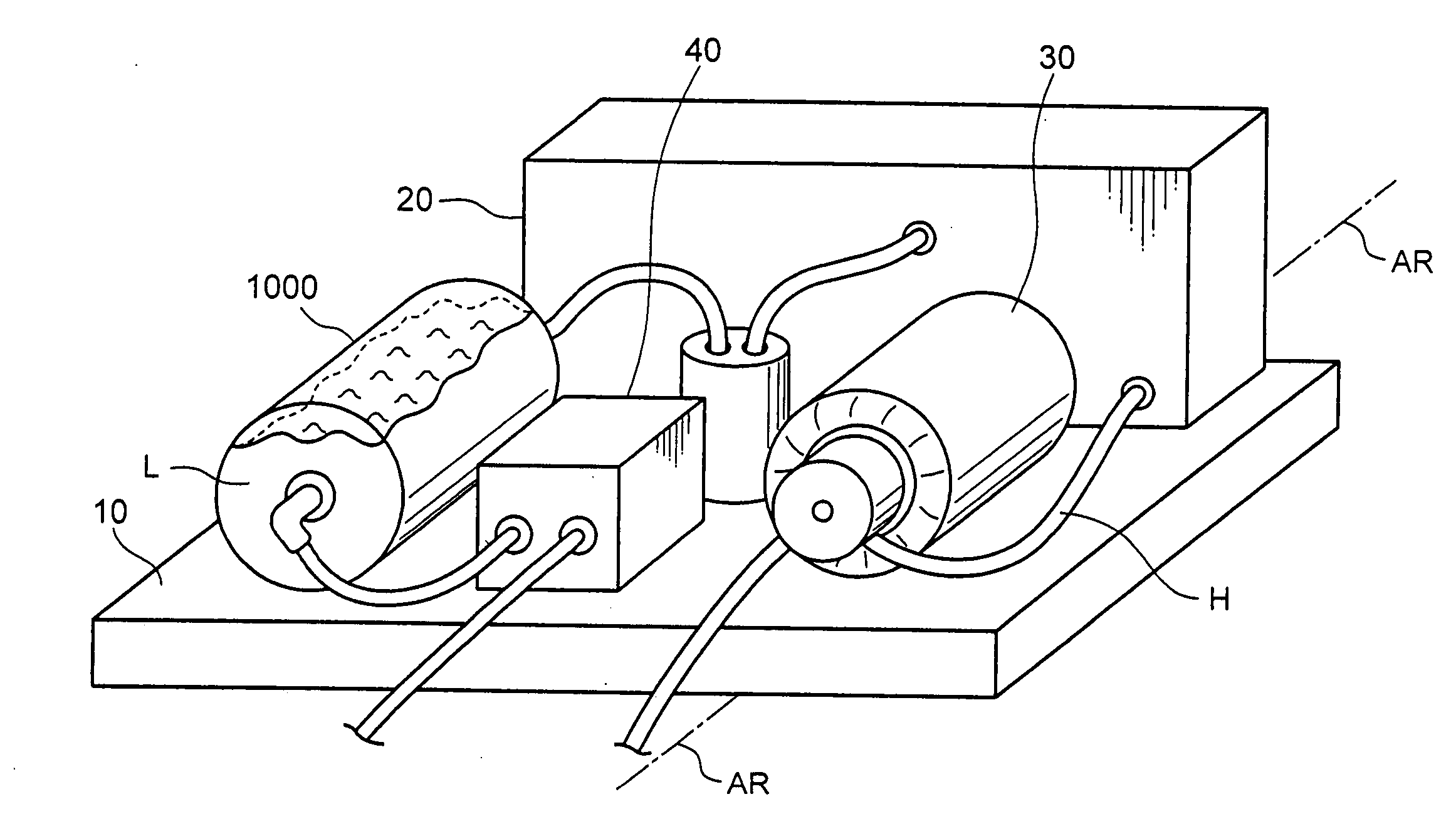
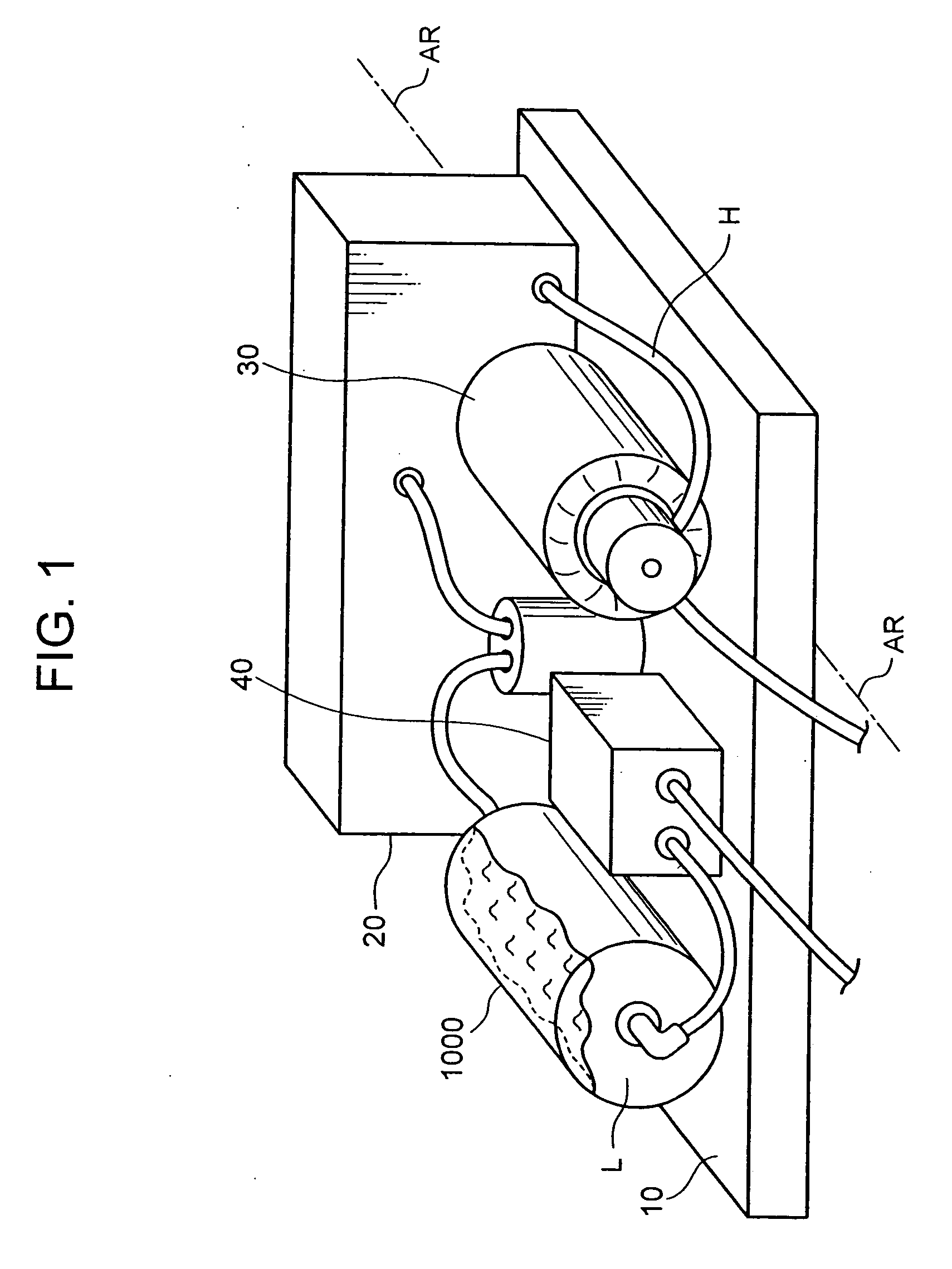
[0026] The system of the invention is depicted in FIG. 1. A rack 10 includes electronics 20 that generates heat and is cooled by a cooling liquid L. The system includes a pump 30, a heat exchanger 40, and various hoses H leading between these components. A tank 1000 contains the cooling liquid L. There are two ports into the tank 100, an inlet port at one end and an outlet port at the other end. Inside the tank 1000 is a degassing and vortex-preventing structure which is described below. Other components, such as an expansion chamber or a filter, can also be employed. The connections of the hoses in FIG. 1 are only exemplary and any sort of liquid path through the system can be used.

[0027] The system shown in FIG. 1 is designed to operate under rotation. An axis of rotation AR is shown in FIG. 1.

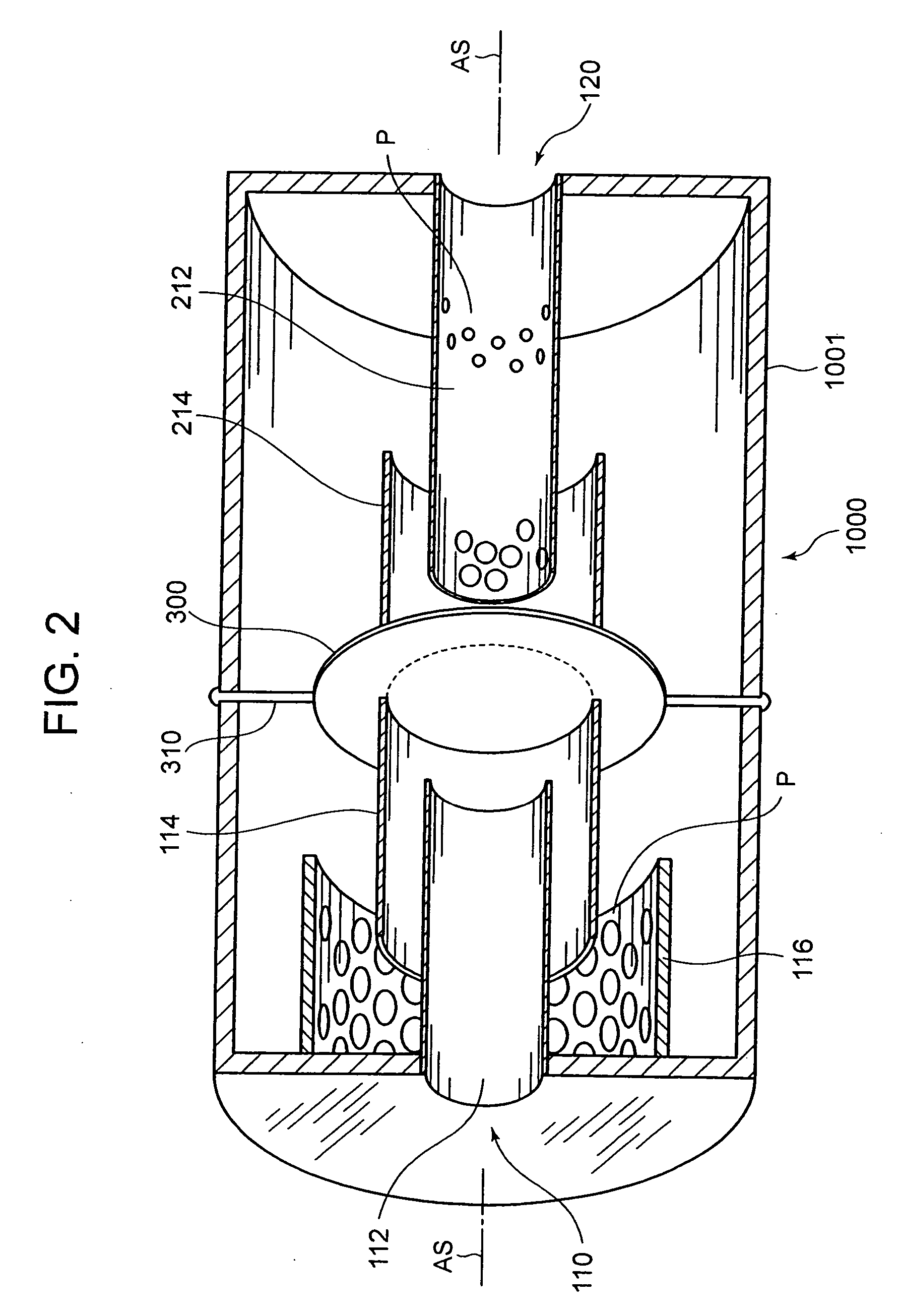
[0028]FIG. 2 best shows the degassing and vortex-preventing structure in a partially cross-sectional view, as if the tank 1000 were sawn down a cylindrical axis of symmetry AS (the axis AS...


PUM


Abstract

In a system for liquid cooling of electronics, where the electronics are subject to rotation in space, a liquid coolant storage tank includes a degassing and vortex-preventing structure to allow bubbles to float to the surface of the liquid inside the tank, and also to prevent vortices from forming near the outlet from the tank. The structure includes nested tubes or conduits. An inner conduit extends from the inlet into the tank, and its open end is covered by a second conduit with a baffle across its end, so that the flow is directed by the baffle to flow back along the outside of the inner conduit, and inside of the outer conduit. Especially at the inlet, a third conduit with large perforations surrounds the open end of the outer conduit. Smaller perforations on the inner conduit at the outlet side discourage any vortex from forming there. Reversal of the liquid flow, and the gradual increase in flow cross section prevent surging inside the tank.

Description

CROSS-REFERENCE TO RELATED APPLICATIONS [0001] There are no related applications. BACKGROUND OF THE INVENTION [0002] The continuing acceleration in computing power demand and supply, with ever-more transistors operating at ever-higher speeds, has brought about the need for liquid cooling of the computer chips. A chip today might contain hundreds of millions of transistors and emit two hundred watts of heat energy (twice the heat output of a 100-watt incandescent light bulb, emitted from a much smaller surface area), and the chip needs intense cooling. When chips are ganged and collected in complex devices, the amount of heat given off can be quite large, so that rooms full of electronic equipment become uncomfortably warm and are difficult to air-condition. Sometimes special air-conditioning must be arranged. For example, large areas of the floor have been converted to air-conditioning vents in some electronic installations [0003] Until recently, most electronic equipment, including...

Claims


Application Information

Patent Timeline
IPC IPC(8): H05K7/20
CPCH05K7/20272H01L2924/0002H01L2924/00
Inventor ECKBERG, ERIC ALANGERKEN, JAMES DORANCEHUETTNER, CARY MICHAELSCHMIDT, ROGER RAY
Owner IBM CORP
Why Eureka
Try Eureka