
Air filtration device

a filter and air technology, applied in chemical/physical/physical-chemical processes, electrostatic separation, chemical/physical processes, etc., can solve the problems of filter inability to remove small viral particles, high concentration of ozone, and high toxicity at high concentrations

Active Publication Date: 2007-04-19
NOVAERUS UK LTD
View PDF99 Cites 5 Cited by
  • Summary
  • Abstract
  • Description
  • Claims
  • Application Information

AI Technical Summary

Benefits of technology

[0041] It will be appreciated that in general where airborne pollutants are being removed from an aircraft cabin or other similar space, the amount of treatment required will depend on the nature of the pollutant, and possibly also the burden or loading thereof in the air. Whilst there may in principle be used multiple passes to progressively reduce the pollutant loading, it is a particular advantage of the invention that the relatively high ozone concentrations which can be achieved with cartridge of the invention within the restricted contained inactivation zone, can usually provide substantially complete inactivation within a single pass, thereby minimizing the number of air changes required and avoiding the risk of cross-infaction amongst passengers. Typically where it is desired to remove bacterial pollutants there should be provided at least 5 air changes per hour, whilst in the case of locations with moderate to high tobacco smoke loadings, it may be desirable to provide at least 10 or more air changes. The total airflow required to treat an aircraft cabin may be readily determined from the volume of the room and the number of air changes required.
that the relatively high ozone concentrations which can be achieved with cartridge of the invention within the restricted contained inactivation zone, can usually provide substantially complete inactivation within a single pass, thereby minimizing the number of air changes required and avoiding the risk of cross-infaction amongst passengers. Typically where it is desired to remove bacterial pollutants there should be provided at least 5 air changes per hour, whilst in the case of locations with moderate to high tobacco smoke loadings, it may be desirable to provide at least 10 or more air changes. The total airflow required to treat an aircraft cabin may be readily determined from the volume of the room and the number of air changes required.

Problems solved by technology

Ozone is, however, highly toxic at high concentrations and it is increasingly clear that even at much lower concentrations it is irritant, being particularly linked with asthmatic complaints in those chronically exposed to it.
Although effective in some situations, such filters suffer from the disadvantages that trapped (and potentially infective) material remains on the filters, necessitating frequent changes of filter and remaining a hazard until the filters are replaced.
This is a particular problem where the air being filtered is humid.
In addition, such filters are incapable of removing small viral particles.
In addition to the abovementioned problems, conventional filtration systems used in aircraft air supply systems in which cabin air is repeatedly recycled with a small proportion thereof being replaced by fresh air from outside the aircraft, present particular problems, due to the extreme temperature ranges encountered.
One significant limitation of HEPA filters is the relatively low face speed thereof, i.e. the maximum airflow speed across the face of the filter at which particles of a given size can be trapped by the filter.
The filter material frequently becomes damp which significantly increases the resistance to the airflow, thereby substantially increasing the load on the air circulation drive, which in turn substantially increases the fuel consumption of the aircraft.
This problem is even further aggravated by freezing of the damp filter material at the very low temperatures encountered at typical airliner cruising altitudes.
A further consequence of such freezing is that it can result in buckling and distortion of the mesh cage which in turn often results in jamming of the filter cartridge inside the cartridge mounting thereby increasing maintenance downtime and cost.
Further research has disclosed, however, that the proposal as disclosed in this publication would be quite impractical—quite apart from exposing the user to dangerous levels of ozone.

Method used


Image

  • Air filtration device
  • Air filtration device
  • Air filtration device

Examples


example 1

Cartridge for use in an Aircraft Air Supply System

Construction

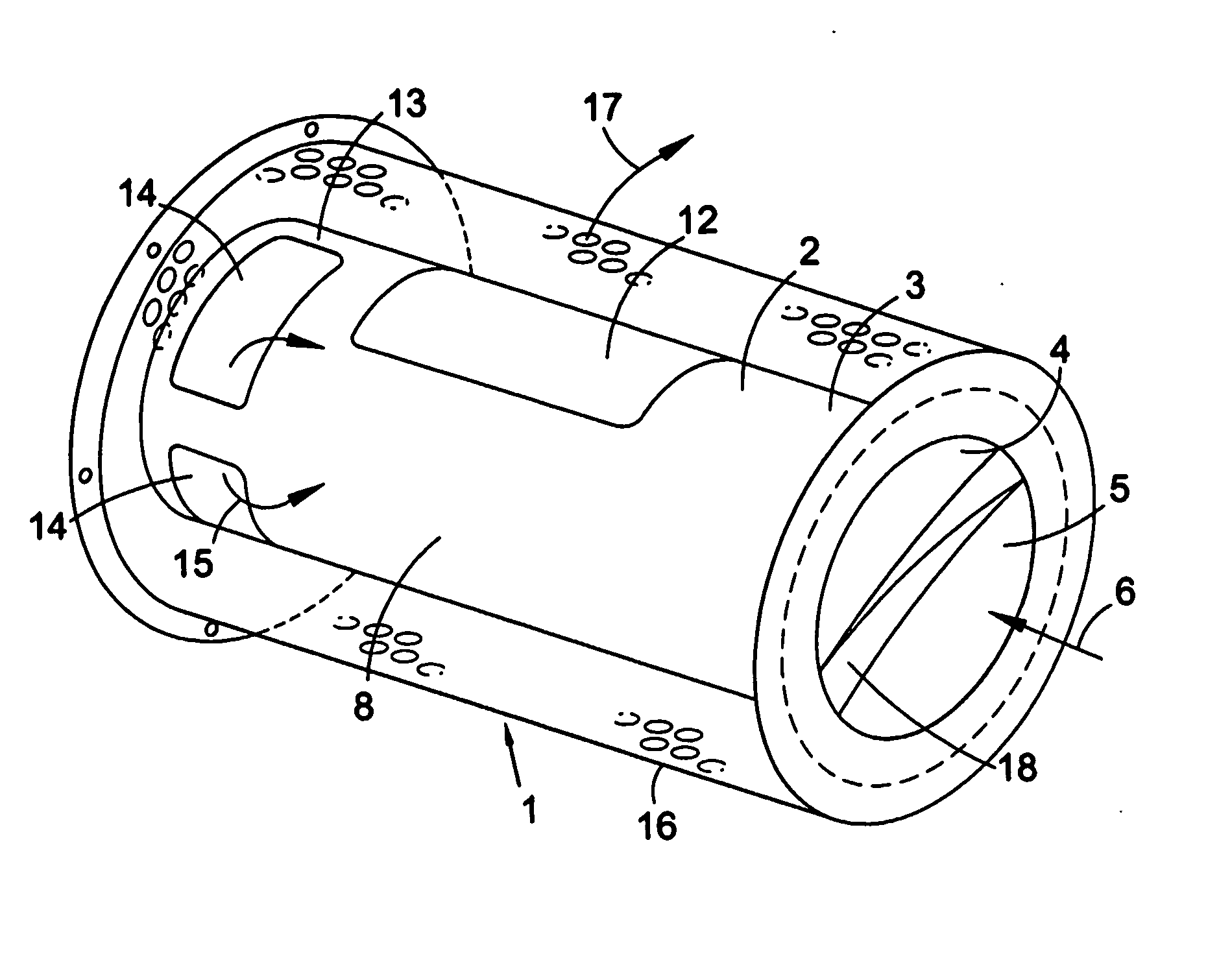
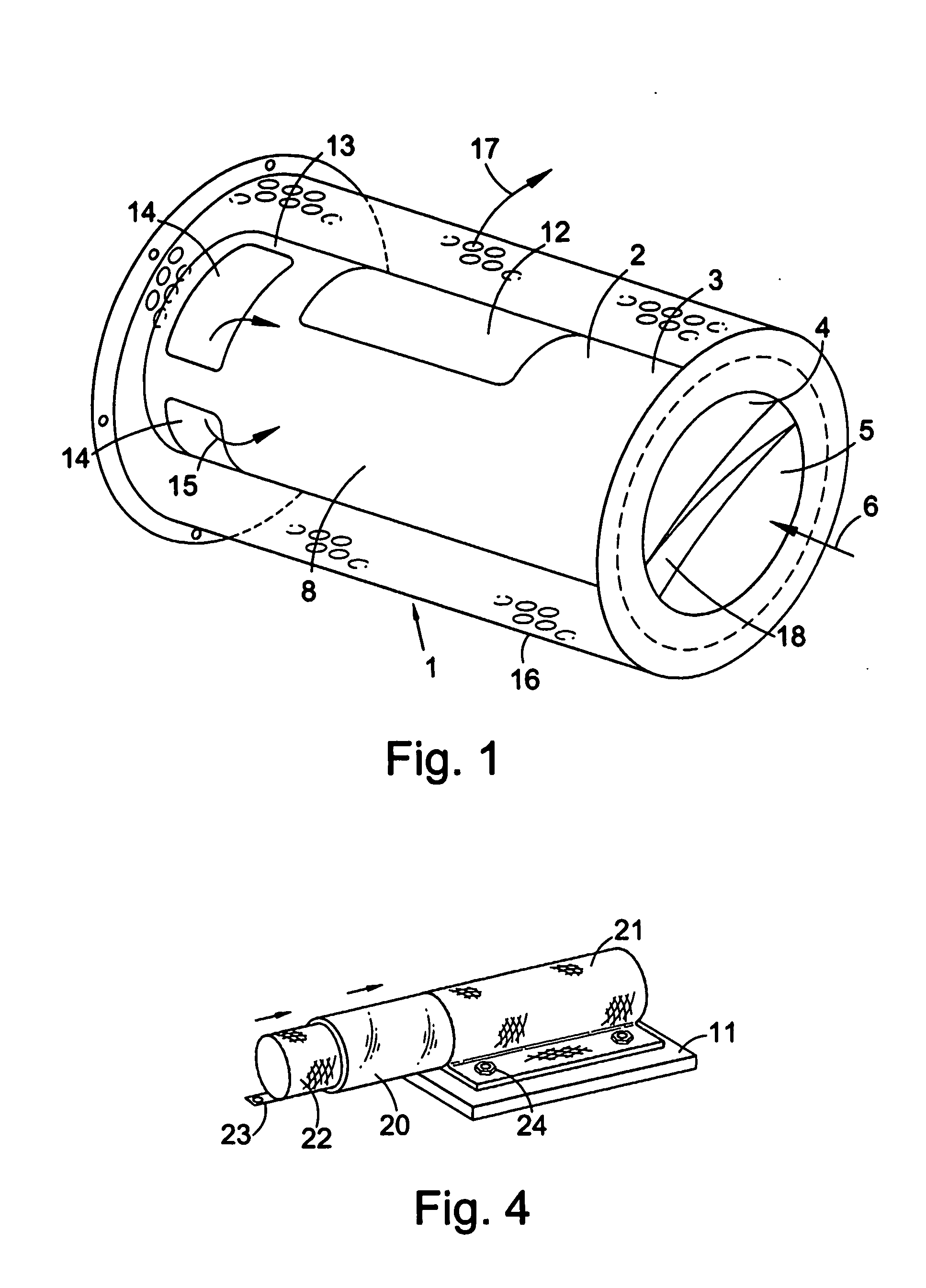
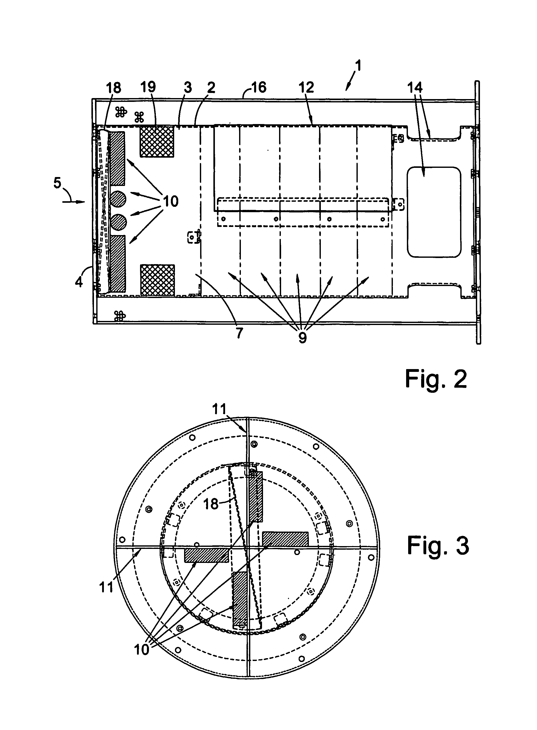
[0047]FIG. 1 shows an air filtration cartridge 1 of the invention suitable for use in the treatment of air in a forced airflow air supply system of an aircraft (not shown). The cartridge 1 comprises an inner casing 2 having an upstream stage 3 defining a chamber 4 having an inlet 5 for receiving a forced airflow 6. The chamber 4 has an outlet 7 which leads into a downstream stage 8 comprising a filter holder and mounting a stack of 10 25 mm thick high airflow electrostatic filters 9 (see FIG. 2), which are preferably 3M Filtrete™ HAF filters.

[0048] Inside the chamber 4 is mounted an array of four generally radially extending angularly distributed low power coronal discharge ozone generator devices 10, supported on insulating material struts 11 (see FIG. 3). The downstream stage 8 is provided with a removable access panel 12 for facilitating insertion and removal of the filters 9. At the downstream end portion 13 of t...

example 2

Anti-Microbial Performance of an M4 / 4 Device

[0053] The invention has been developed into a range of devices designed for microbiological decontamination of atmospheres. This embodiment employs closed-coupled field technology for the contained generation of an oxidising field, in tandem with electrostatic filtration of the air stream. Combining these technologies in a manner that affords a high flow-rate permits the effective treatment of large volumes of atmosphere.

M4 / 4 Device

[0054] This embodiment of the invention comprises four fans connected and switched so as to be progressively activated in order to provide a range of airflow rates: [0055] Speed 1=160 m3 / hour Speed 2=320 m3 / hour [0056] Speed 3=480 m3 / hour Speed 4=540 m3 / hour

[0057] Two modes of filtration were used in various experiments. Either a HEPA filter or an HAF (3M Filtrete™) post-filter were fitted and their relative effects compared.

Ozone Production Characteristics

[0058] The European standard for atmospheric l...

example 3

Single Pass Anti-Microbial Competence of M4 / 4 Device

[0065] The following experimental data reports on the performance of the device in relation to the reduction of single pass microbial challenges. Performance at each of four flow rates has been determined for a range of organisms with electrostatic filtration in place.

TABLE 4M4 / 4 single pass performance with electrostatic filtrationChallengeSpeed 1Speed 2Speed 3Speed 4levelRecoveryRecoveryRecoveryRecoveryOrganismcfu / l-1cfu / l-1cfu / l-1cfu / l-1cfu / l-1A. niger8.80E+06S.7.40E+06C. albicans6.00E+06S. aureus7.10E+06B. cereus2.20E+061.30E+02


PUM

PropertyMeasurementUnit
power ratingaaaaaaaaaa
concentrationaaaaaaaaaa

Abstract

The present invention provides an air filtration cartridge 1 suitable for use in the treatment of air in a forced airflow air supply system. The cartridge 1 comprises an inner casing 2 having an upstream stage 3 defining a chamber 4 having an inlet 5 for receiving a forced airflow 6. The chamber 4 has an outlet 7 which leads into a downstream stage 8 comprising a filter holder and mounting a high airflow electrostatic filter. Inside the chamber 4 is a low power coronal discharge ozone generator device 10.

Description

FIELD OF THE INVENTION [0001] The present invention relates to an apparatus and method for the removal of airborne pollutants or impurities such as micro-organisms, smoke particles or odours from air by means of transient treatment of the air in a low power corona discharge field, in forced air-flow air-conditioning systems, especially in situations such as aircraft and submarines etc where the air is recirculated many times. BACKGROUND TO THE INVENTION [0002] The use of ozone in many applications involving sterilising and cleaning air is well known. Ozone generating devices have been designed for a great variety of domestic and industrial applications. All depend on ozone's great oxidising potential to kill micro-organisms and oxidise other organic particles and materials. Depending on the application, ozone is generated by means of ultraviolet radiation or electrical discharge to convert atmospheric oxygen to triatomic ozone, which can be highly effective at destroying organic atm...

Claims


Application Information

Patent Timeline
Patent Type & Authority Applications(United States)
IPC IPC(8): B01J19/08F24F8/26
CPCA61L9/015B01D46/0028B01D46/50B01D53/32B01D53/323B01D2251/104B01D2257/90B01D2257/91B03C3/09B03C3/383B03C3/49C01B13/11C01B2201/14C01B2201/34F24F3/16F24F2003/1685Y02A50/20F24F8/40F24F8/26
Inventor HALLAM, DAVID RICHARD
Owner NOVAERUS UK LTD
Learn More