
Fine steel cord with a low structural elongation

a technology of structural elongation and fine steel, which is applied in the direction of yarn, mechanical equipment, coatings, etc., can solve the problems of ‘dimensional control, premature wear of belts or even teeth jumping out of gears, and insufficient tolerances as set forth in din 7721 standard, so as to increase the overall modulus of cords and reduce the elongation of belts

Inactive Publication Date: 2007-04-26
NV BEKAERT SA
View PDF15 Cites 6 Cited by
  • Summary
  • Abstract
  • Description
  • Claims
  • Application Information

AI Technical Summary

Benefits of technology

[0011] The inventors have found a different solution to solve the ‘dimensional control problem’ of synchronous belts, which is a first object of the invention. Surprisingly their solution also solved the ‘curling’ and ‘sabre’ effect. In addition their solution also increased the overall modulus of the cord in the working region of the belt thus reducing the elongation of the belt between loaded and unloaded part of a belt cycle without having to use more reinforcement material: a second object of the invention. The inventors have found a method to produce the multi strand cords in an efficient way: a third object of this invention.
[0042] The penetration of the elastomer greatly helps to keep the filaments ‘in place’ during their use. It is therefore preferred that the elastomer penetrates at least the outer strands of the cord. Most preferred is that all individual filaments are completely surrounded by polymer over substantially the length of the fine cord (claim 13).
[0047] The second aspect of the invention concerns a method to produce the inventive cord. According this method the needed strands are produced having a number of twists ns of at the most Ns i.e. the number of twists the filaments must have in the strand of the final cord. Each of the necessary strand spools is mounted in an individual twister pay-off. A twister pay-off is a pay-off system that is able to increase the number of twists per unit length in the strand when turning in the same lay direction of the strand. Mutatis mutandis, the twister pay-off is able to reduce the number of twists per unit length of the strands when it is turning in the direction opposite to the lay direction of the strand. The number of twists added or subtracted is proportional to the ratio of rotational speed of the twister to the linear speed of the strand. Preferably the rotational speed is adjustable. Most preferable is that both speeds are adjustable.
[0051] A second important feature of the method is that the entrance pulley of the bunching machine must be put under an angle with respect to the plane formed by entering and exiting cord (claim 8). After this pulley the cord is guided in a bow towards the reversing pulley at the end of the bow. Preferentially these pulleys are grooved. Even more preferred is that these pulleys have a U shaped grove larger than the diameter of the cord. Normally the rotational axis of the entrance pulley is perpendicular to the plane formed by entering an exiting cord i.e. directed along the normal of that plane. According to the invention the entrance pulley axis is inclined with respect to this normal. The inclination is set such that the cord rolls in the U shaped groove in its closing direction. The closing direction is the rotational direction in which the number of twists on the cord increases. More preferred is that the axis of the pulley is rotated around the bisector of the lines formed by the entering and exiting cord. Even more preferred is that both entrance and reversing pulley are put under an angle (claim 8). The principle of putting the entrance and reversing pulleys under angle is to shift the point where the strands in the cord obtain their final number of twists to the assembly point. In this way the untwisting of the strands in the bow of the bunching machine is prevented. For clarity: in a state-of-the art bunching machine (no pulleys under angle) the cord receives half of its final number of twists at the entrance pulley and the other half of its final number of twists at the reversing pulley. Hence the strand is untwisted during its travel in the bow of the bunching machine while it gets its final position in the cord. In the cord the strand is thus fixed in a loosened state causing again too high structural elongation, which on its turn leads to the dimensional control problem of synchronous belts.

Problems solved by technology

In practice the tolerances as set forth by the DIN 7721 standard are not longer sufficient as uses of synchronous belts are spanning longer distances or require better precision control.
Any misfit during engagement of the tooth into the gear recess will lead to premature wear of the belt or even teeth jumping out of the gear.
The problem of ‘dimensional control’ has thus emerged for synchronous belts.
These forces are not high enough to completely eliminate the structural elongation.
Upon pre-tensioning the synchronous belt between the toothed wheels the remaining structural elongation of the cords will lead to out of specification tooth pitch and the problems associated with this.
Both of these solutions have their drawbacks in terms of more rejects and / or more expensive belts.
However, with increasing width the synchronous belt production is more susceptible to the ‘curling’ effect (when hanging a piece of the belt freely, the free end turns with respect to the fixed end) or the ‘sabre’ effect (a piece of the belt laid down on a flat surface is not straight, but curved).
Both effects are very detrimental in the use of the belt, as they tend to derail the belt from the gear wheel.

Method used


Image

  • Fine steel cord with a low structural elongation
  • Fine steel cord with a low structural elongation
  • Fine steel cord with a low structural elongation

Examples


Embodiment Construction

[0061] In a first preferred embodiment, the inventors have produced a 7×3 type of cord characterised by the following formula:

[(3×0.15)9 s+6×(3×0.15)9 s]8 Z

i.e. a core strand consisting of 3 filaments twisted together with a lay length of 9 mm in S direction is combined with 6 outer strands again consisting of 3 filaments twisted together with a lay length of 9 mm in S direction to a cord. The strands are twisted in to the cord with a lay length of 8 mm in Z direction. The filaments were plain carbon steel filaments having a carbon content of about 0.725 wt. % C and having a hot dip galvanised zinc coating. The cord was produced from the filaments according the conventional process and the inventive process. The cord has a metal cross-sectional area of 0.371 mm2 (acc. DIN 3051 i.e. sum of filament cross sections).

[0062] First the conventional process will be explained by means of FIG. 4a. Thereafter the inventive changes to this process will be highlighted. A strand spool 2—cont...


PUM

PropertyMeasurementUnit
structural elongationaaaaaaaaaa

Abstract

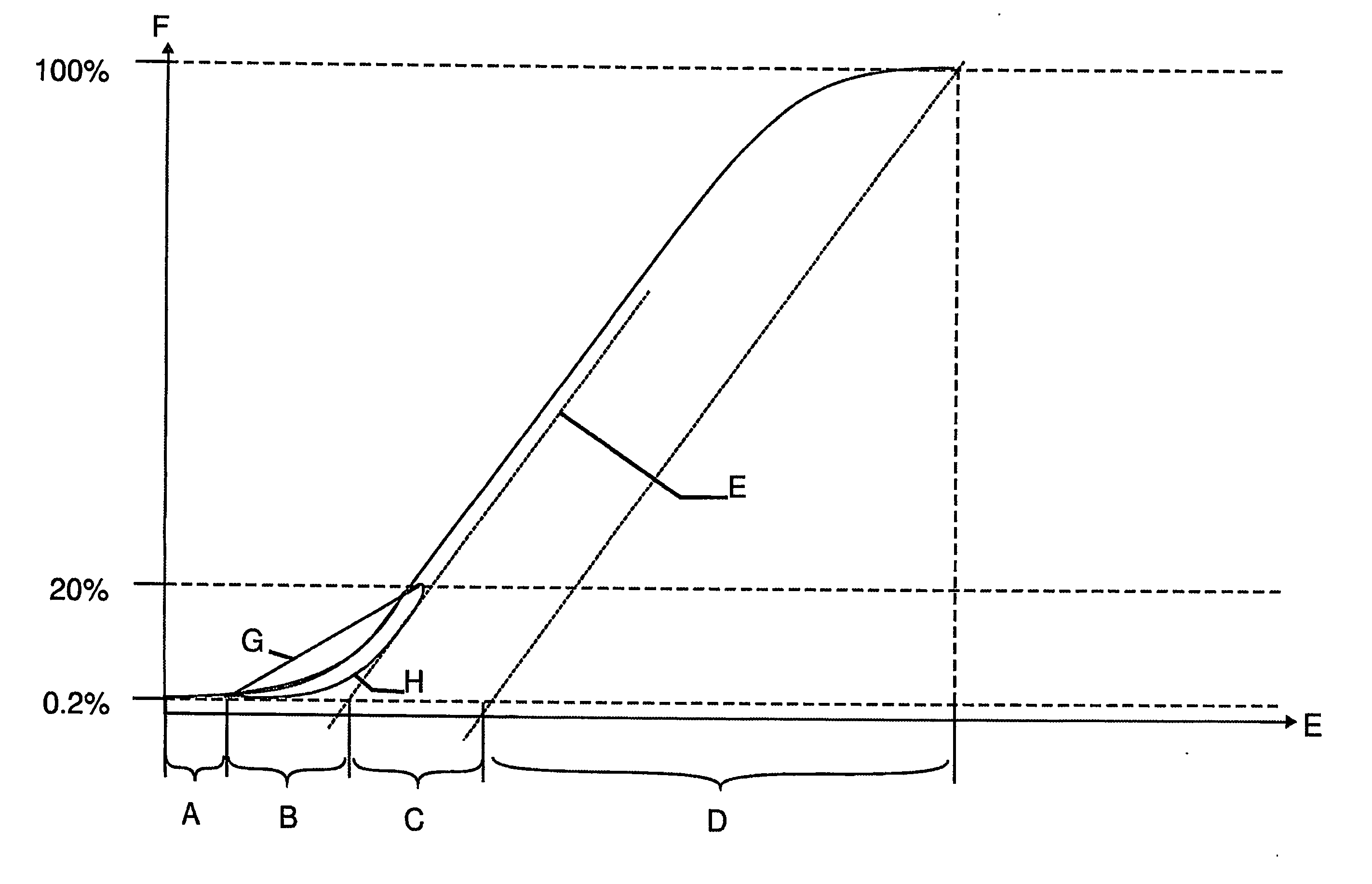
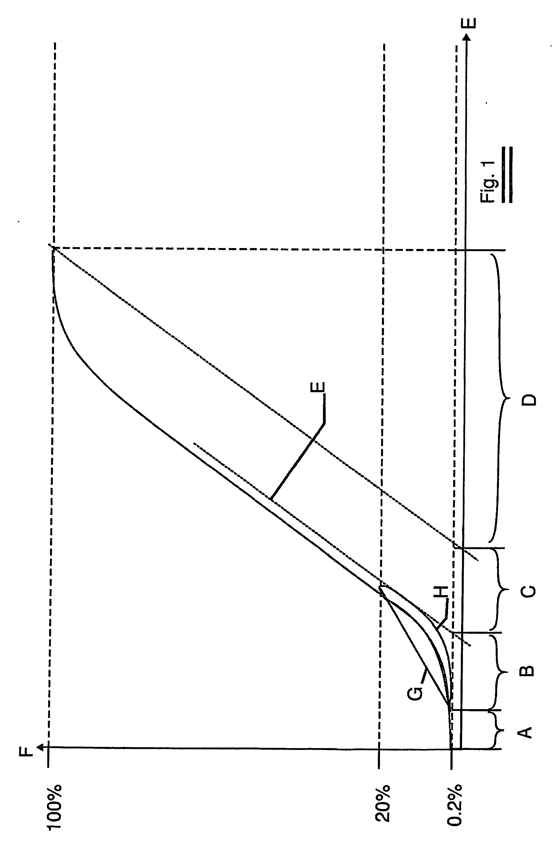
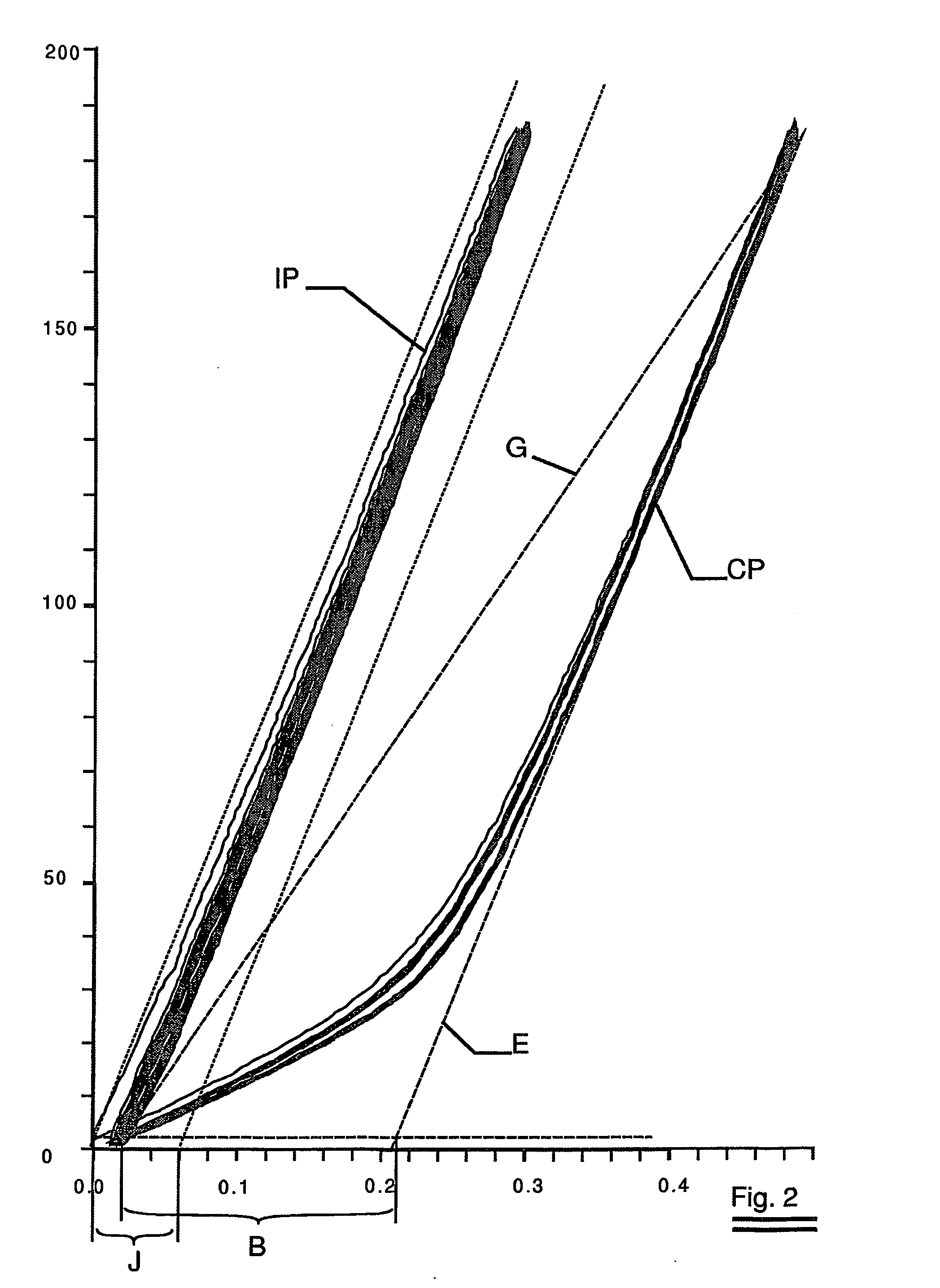
A fine steel cord for the reinforcement of synchronous belts is presented. The fine cord has a distinct load elongation curve characterized by a very low structural elongation (below 0.09% preferably below 0.06%), and a high equivaslent modulus between 0.2 and 20% of the breaking, load. The favorable results are maintained when the cords are coated with an elastomer coating. Such a fine steel cord reduces the geometrical spread on the tooth pitch of the synchronous belts during use. A method to produce such a fine steel cord is also presented.

Description

FIELD OF THE INVENTION [0001] The invention relates to a fine steel cord for reinforcing a synchronous belt. BACKGROUND OF THE INVENTION [0002] Synchronous belts have found their way in many precision machines; in automobiles, in computer peripheral apparatus such as printers and copying machines, in positioning systems and in many other applications. In the art they are also known under other names such as ‘toothed belts’, ‘transmission belts’ or ‘timing belts’. In what follows, the terms and definitions according the standard ISO 5288-1982 will be adhered to. Industry standards DIN 7721-1989 and ISO 5296-1: 1989 define the sizes and tolerances of commercially available synchronous belts. Synchronous belts are applied where power transmission or precise longitudinal continuous or stepped displacement of the belt or precise angular positioning over a longer distance is of the essence. One of the main requirements posed to a synchronous belt is the tolerance on the pitch length (see ...

Claims


Application Information

Patent Timeline
Patent Type & Authority Applications(United States)
IPC IPC(8): D02G3/02D07B1/06D07B3/00F16G1/12F16G1/28
CPCD07B1/0613D07B3/00D07B2201/2044D07B2205/2064D07B2207/203D07B2207/205D07B2401/201D07B2501/2076F16G1/28D07B2801/18D07B2207/208D07B1/0693D07B2201/104D07B2401/202D07B2501/20
Inventor VANCOMPERNOLLE, STIJNBRUYNEEL, PAULVANDERBEKEN, BERT
Owner NV BEKAERT SA
Learn More