

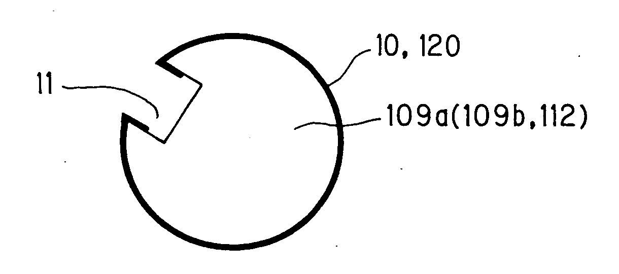
Jacket for impression cylinder or transport cylinder of printing press
- Summary
- Abstract
- Description
- Claims
- Application Information
AI Technical Summary
Benefits of technology
Problems solved by technology
Method used
Image

Examples
example 1
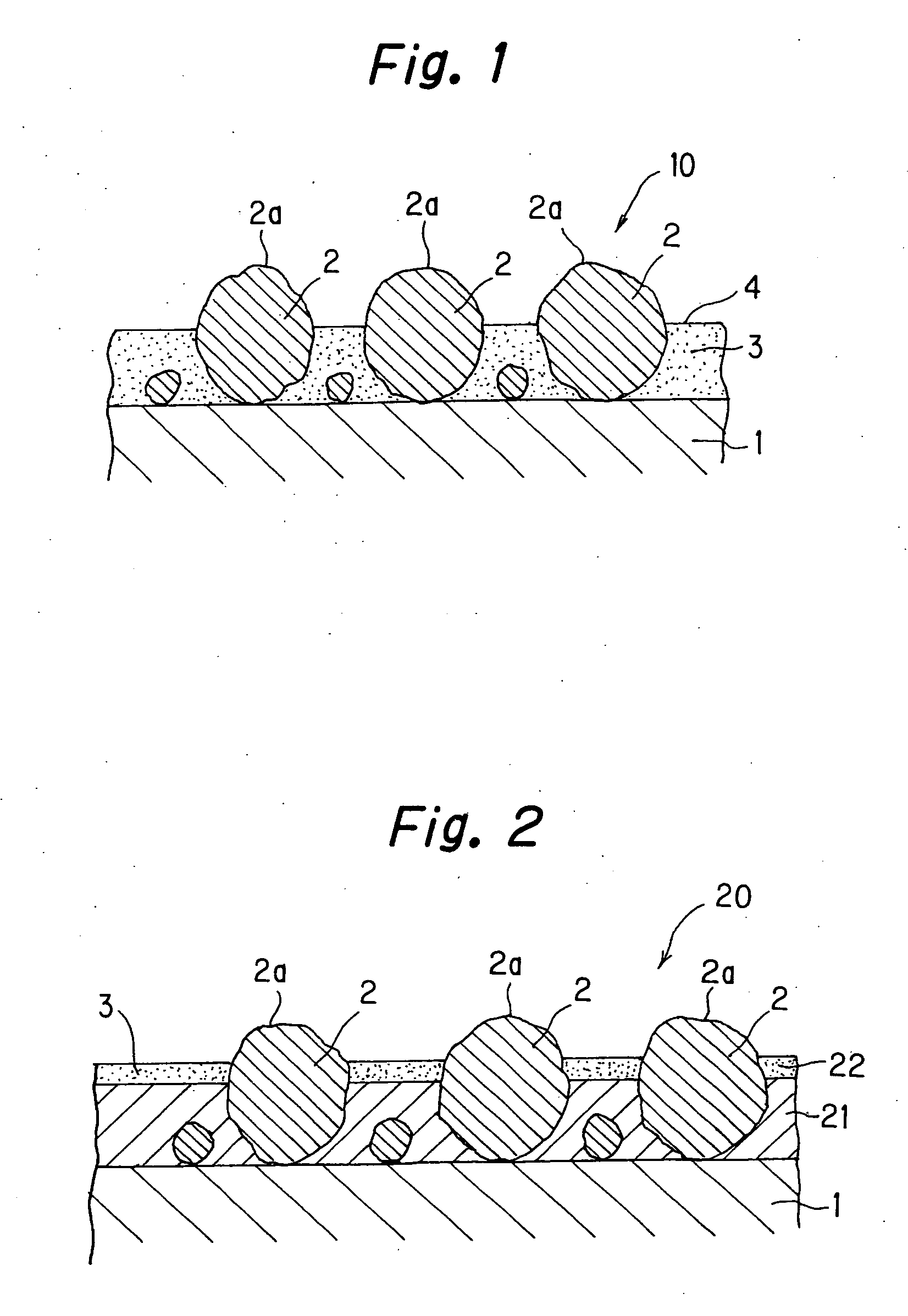
[0033] As shown in FIG. 1, super hard particles 2 are scattered on a sheet-shaped base member 1. As the sheet-shaped base member 1, for example, a stainless steel plate or a corrosion-resistant metal plate of aluminum or the like is adapted. As the super hard particles 2, the following particles can be used; ceramic particles, amorphous alloy particles, diamond particles, tungsten particles, and molybdenum particles, and furthermore, particles of oxide or carbide tungsten, molybdenum, boron, aluminum, titanium, and silicon, or particles of glass.
[0034] The super hard particles 2 having an average particle diameter in a range from 3 μm to 30 μm are adapted. In a case where the super hard particles 2 having an average particle diameter less than 3 μm are used, the surface roughness of the jacket becomes too small. For this reason, the ink adheres to the surface of the jacket, causing smearing. On the other hand, when the average particle diameter of the super hard particles 2 is grea...
example 2
[0052] As shown in FIG. 2, a jacket 20 according to this example is the same as that of Example 1 as to the following point. Both of the jackets 10, 20 are formed in the same manner that the super hard particles 2 such as ceramic particles are scattered on the base member 1. In this example, however, the super hard particles 2 are first fixed onto the base member 1 by nickel (Ni) plating (first plating), instead of coating the surface with the composite plating where the fine particles of low surface energy resin is dispersed. The super hard particles 2 are firmly fixed onto the base member 1 by this nickel plating layer (a first plating layer) 21. Next, a composite plating (a second plating) using nickel-phosphorus (Ni—P) containing PTFE fine particles 3 is processed thereon in a manner where a half or more of the height of each of the super hard particles 2 is covered. In this case, a nickel-phosphorus plating layer (a composite plating layer) 22 formed by the second plating can b...
example 3
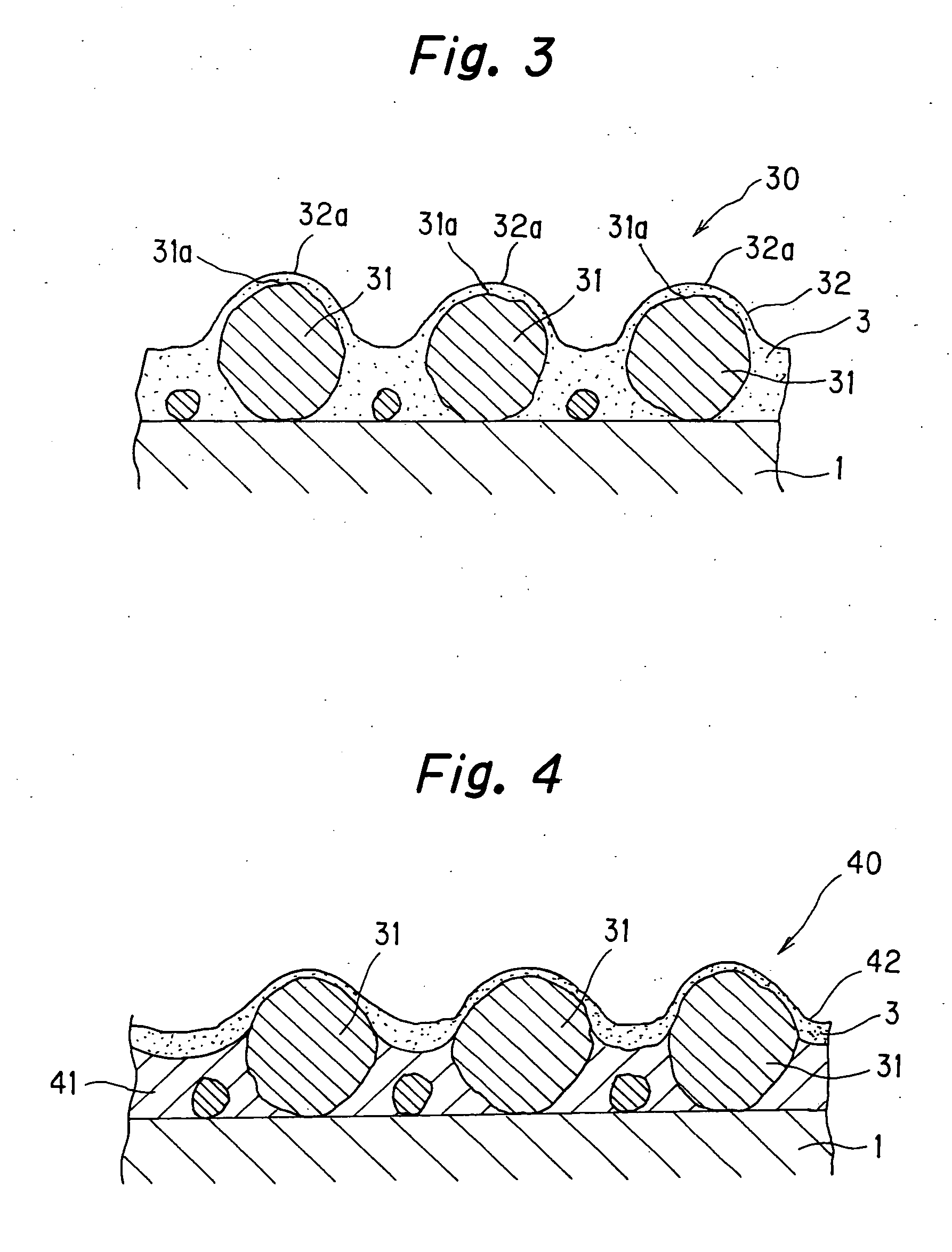
[0054] As shown in FIG. 3, a jacket 30 according to this example is configured in a manner that a top surface portion of each super hard particle 31 is coated with a plating layer. This structure is formed as follows. Corroded ceramic particles 31 are scattered onto the base member 1. Subsequently, a composite plating 32 is formed thereon, in which the fine particles of low surface energy resin are uniformly dispersed.
[0055] As shown in FIG. 3, the surface of each of the ceramic particles 31 is coated with the composite metal layer 32, and a convex and concave profile is formed as a whole. In this example, material of the base member 1, the low surface energy resin, and metal material forming the composite plating 32 containing the fine particles, are same as those in Example 1. Furthermore, particle diameters and the average particle size of the ceramic particles 31, and a volume ratio of the low surface energy resin in the composite plating 32, particle diameters of the fine part...
PUM
 Abstract
Description
Claims
Application Information