

Method and system for controlling power consumption during a rock drilling process and a rock drilling apparatus therefore
- Summary
- Abstract
- Description
- Claims
- Application Information
AI Technical Summary
Benefits of technology
Problems solved by technology
Method used
Image

Examples
Embodiment Construction
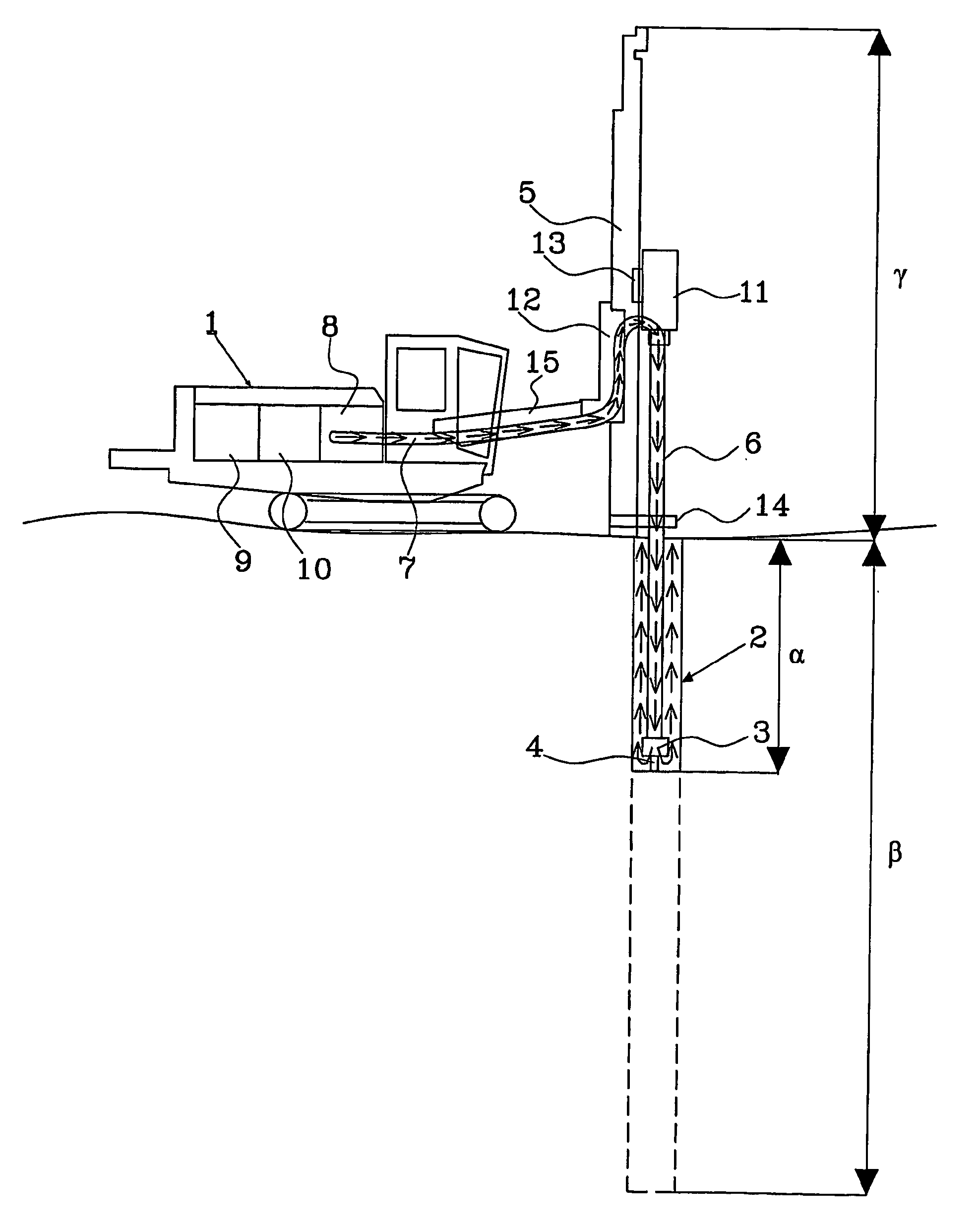
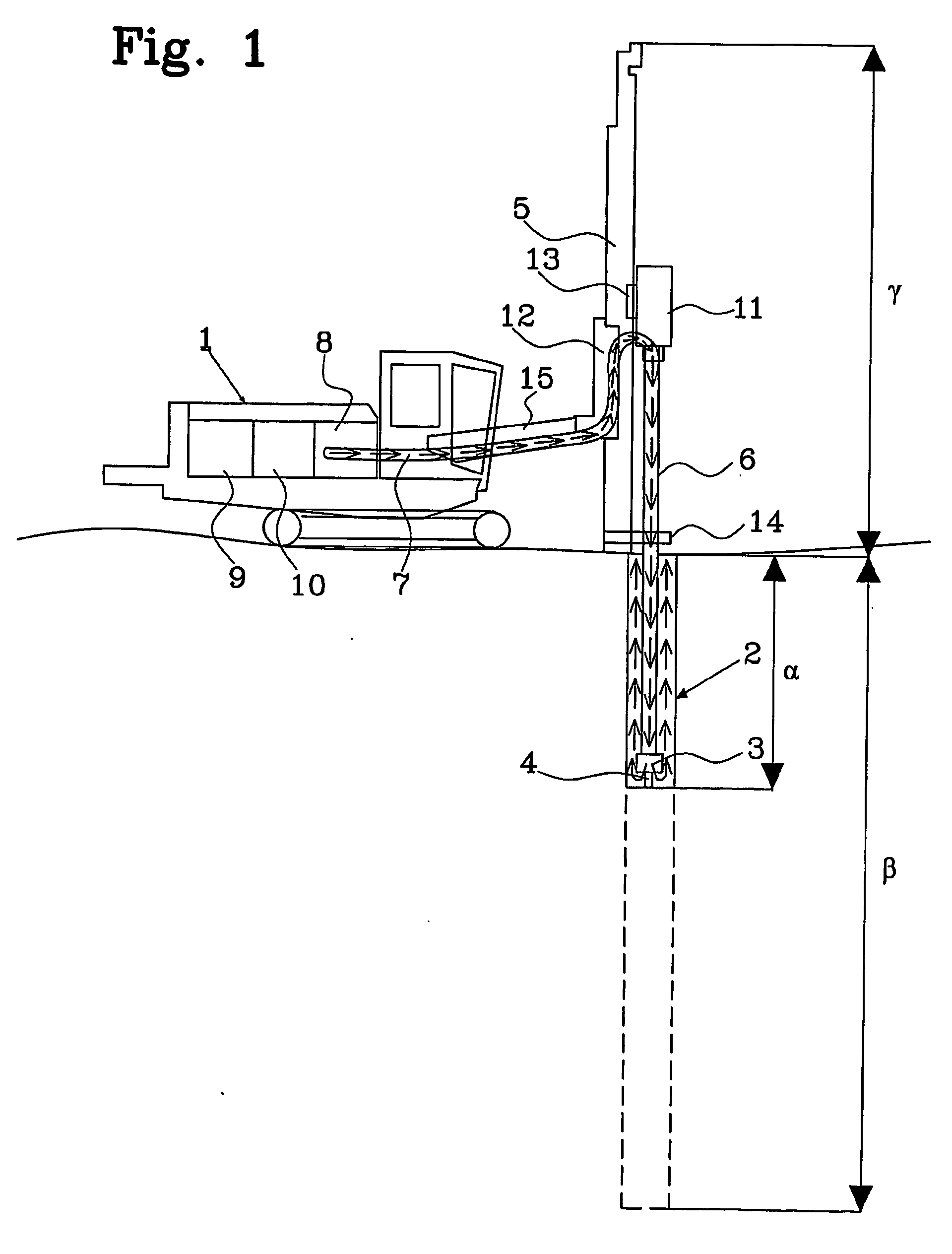
[0023]FIG. 1 depicts an exemplary rock drilling apparatus according to the present invention. In the figure is shown a rock drilling apparatus 1, in this exemplary a surface drill rig. The drill rig 1 is shown in use drilling a hole 2, starting from a ground level, at present having reached a depth α and destined to result in a hole of depth β, for example 30 meters, the finished hole being indicated by interrupted lines. (The shown relation of drill rig height / hole depth is not intended to be exact. The total height γ of the drill might for example be 10 meters.)
[0024] The drill rig 1 is provided with a top hammer 11 mounted via a rock drill cradle 13 on a feed 5. The feed 5 is attached to a boom 15 via a feed holder 12. The top hammer 11 provides percussive action to a drill tool 3 with one or more drill bits 4 via a drill rod 6 supported by a rod support 14. The top hammer 11 is power supplied from a hydraulic pump 10, driven by a diesel engine 9, via a conduit attached to the f...
PUM
 Abstract
Description
Claims
Application Information