Glass cutting method and apparatus therefor

a cutting method and glass technology, applied in glass making apparatus, stone-like material working apparatus, manufacturing tools, etc., can solve the problems of affecting the post-processing process, such as shavings, and unable to generate dust and the like, and achieve the effect of rapid and accurate formation, high photon energy, and efficient formation

Inactive Publication Date: 2007-04-26
JAPAN STEEL WORKS LTD
View PDF2 Cites 46 Cited by
  • Summary
  • Abstract
  • Description
  • Claims
  • Application Information

AI Technical Summary

Benefits of technology

[0018] According to the invention as claimed in each of independent claims 1 and 5, in forming a scribe line by irradiating a portion of glass to be cut with a pulse laser, an ultraviolet pulse laser is used, the total number of pulses at each irradiation portion of glass is set in a range of 2,667 to 8,000 pulses, and the scribe line is formed to a depth corresponding to 1.8 to 6.3% of the thickness of the glass.
[0019] As a result, a scribe line with a predetermined depth is formed by irradiating an ultraviolet pulse laser with suitable thermal energy a number of times, whereby the adhesion of re-molten glass to the inside of a scribe groove and the occurrence of sawtooth-shaped cracks in a bottom surface can be suppressed satisfactorily. Fur

Problems solved by technology

Therefore, dust and the like to be an obstacle in a post

Method used


Image

  • Glass cutting method and apparatus therefor
  • Glass cutting method and apparatus therefor
  • Glass cutting method and apparatus therefor

Examples


embodiment

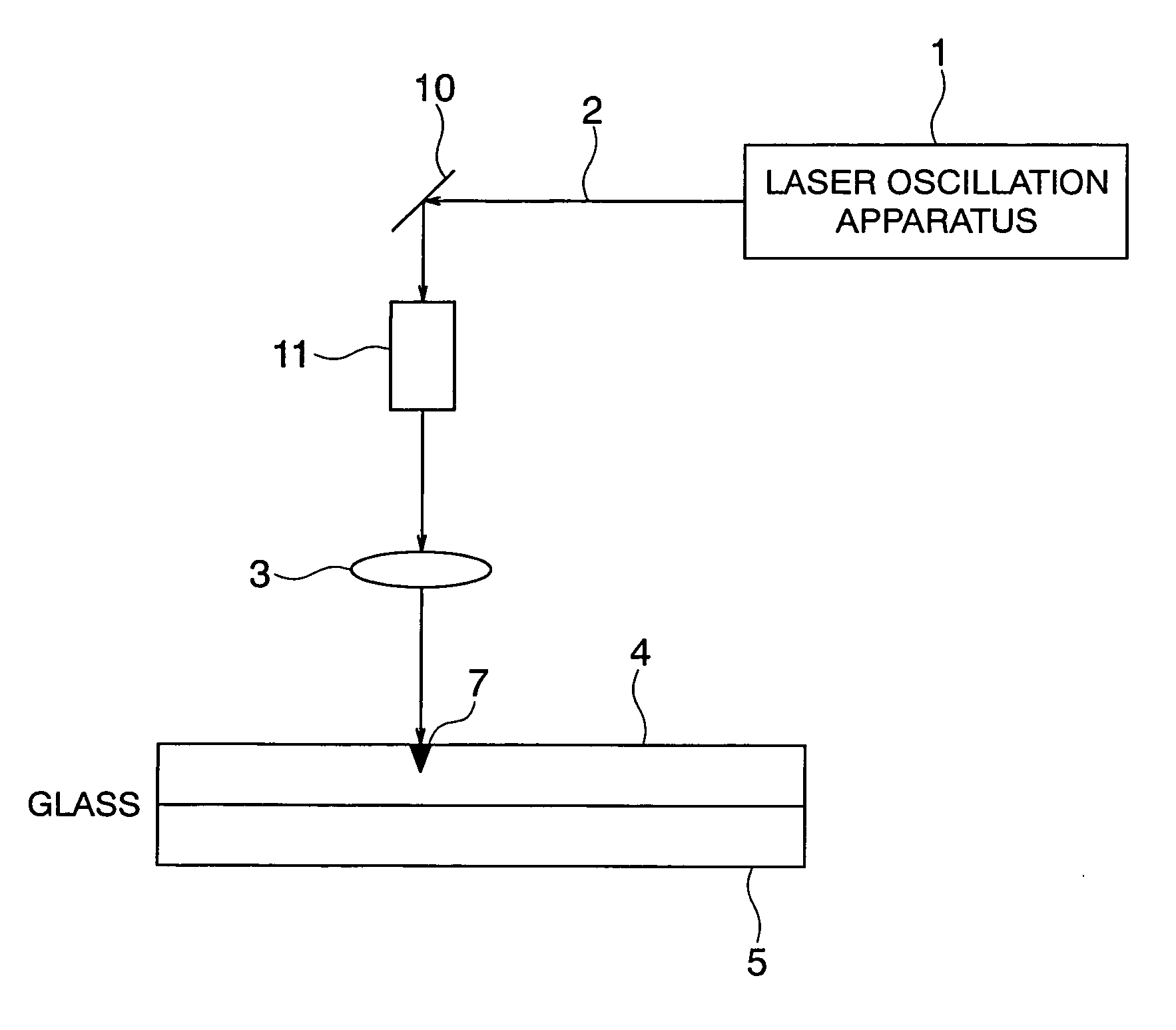
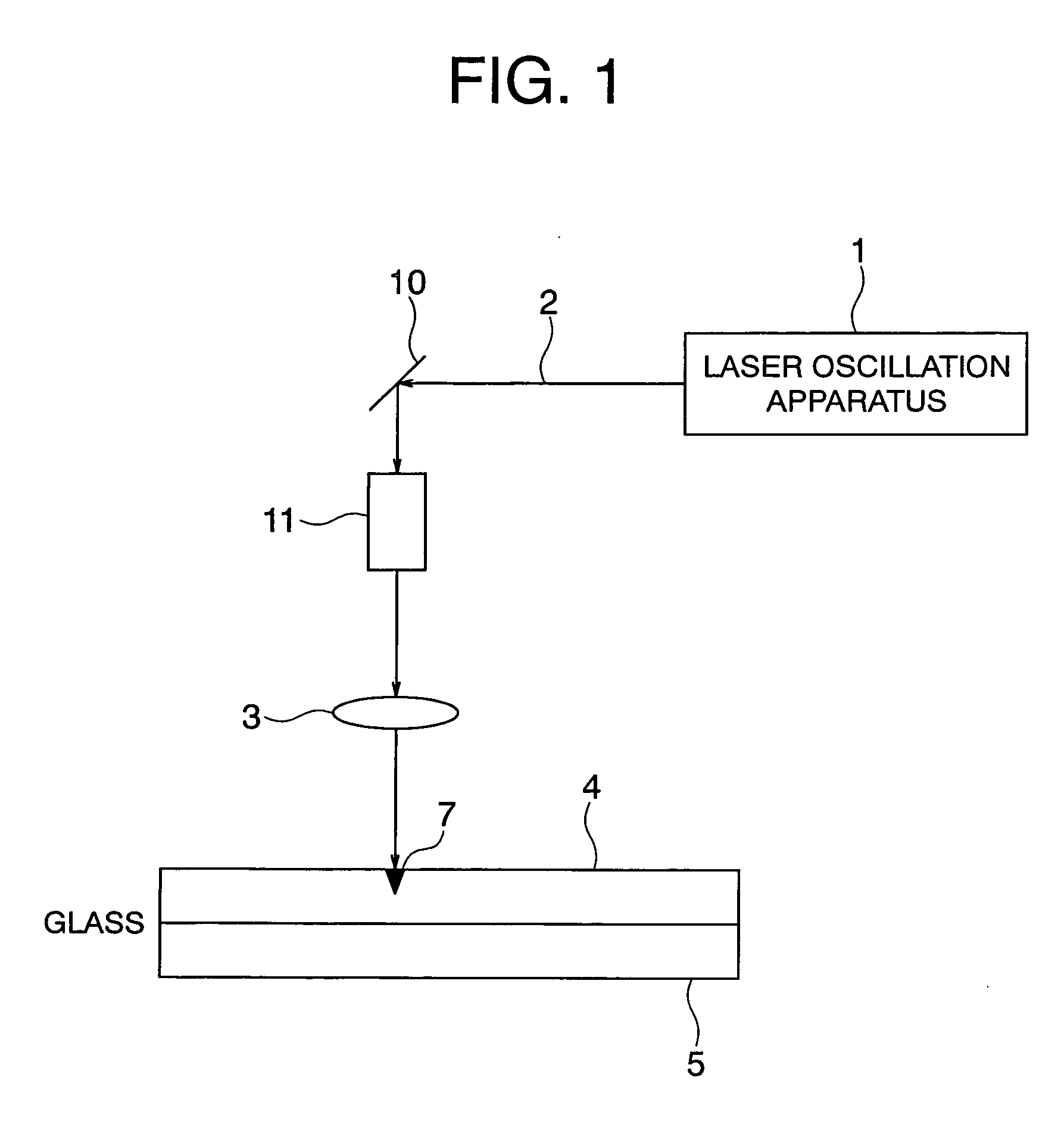
[0033] FIGS. 1 to 9 show an embodiment mode of a glass cutting apparatus according to the present invention. In FIG. 1, reference numeral 1 denotes a laser oscillation apparatus. The laser oscillation apparatus 1 emits a pulse laser 2 composed of an ultraviolet laser having a pulse width of less than 100 picoseconds (for example, τ=15 ps as shown in FIG. 9(B)). The repetition frequency of the pulse laser 2 is 10 MHz (10×106 Hz) or more (for example, f=80 MHz as shown in FIG. 9(B)). As the pulse laser 2 of an ultraviolet range, the third harmonic, the fourth harmonic, or the fifth harmonic of an Nd:YAG laser, Nd:YVO4 laser, or Nd:YLF laser can be used. Those ultraviolet lasers with a short wavelength have large energy of one photon, and can be photochemically decomposed. If irradiated for an appropriate time and number of times at an appropriate energy density, these lasers are capable of performing minute processing with precision having less thermal influence on the surroundings.

[...


PUM

PropertyMeasurementUnit
Fractionaaaaaaaaaa
Timeaaaaaaaaaa
Frequencyaaaaaaaaaa

Abstract

In the case of forming a scribe line by irradiating a laser in an ultraviolet range in one stroke, the glass bending strength after glass is cut is about 50 MPa or less, and the glass is likely to be subjected to crack damage during use as liquid crystal panel glass or the like. In a glass cutting method in which a portion to be cut of glass 4 is irradiated with a pulse laser 2 in one stroke of relative movement to form a scribe line 7, and then the glass is cut by applying a break force to the scribe line 7, a pulse laser of an ultraviolet range is used as the pulse laser 2, and the pulse laser 2 is irradiated while the pulse laser 2 is being relatively moved so that the total number of pulses at each irradiation portion is in a range of 2,667 to 8,000 pulses, whereby the scribe line 7 is formed to a depth of 1.8 to 6.3% of the thickness of the glass 4.

Description

TECHNICAL FIELD [0001] The present invention relates to a glass cutting method and an apparatus therefor, and more specifically, to a glass cutting method using pulse laser light of an ultraviolet range and an apparatus therefor. BACKGROUND ART [0002] As a conventional, typical glass cutting method, as shown in FIG. 11, the following is known: a scribe line (notch line) 62 is formed on a front surface of glass 60 with a blade 61 such as a diamond blade or a super-hard blade, and thereafter, a break force (shock separation force) 63 is applied from a rear surface thereof to cut the glass 60 along the scribe line 62. [0003] A glass cutting method using a laser is also known. [0004] A method disclosed in Patent Document 1 involves, as shown in FIG. 12, irradiating the glass 60 with an infrared laser 74 shaped in an oval shape and transmitted through the glass with relative ease, and the vicinity of a rear side of a laser-irradiated portion is cooled with a refrigerant 75 (aqueous coola...

Claims


Application Information

Patent Timeline
IPC IPC(8): B23K26/38B28D5/00B23K26/00B23K26/364C03B33/02C03B33/023C03B33/09
CPCB23K26/367C03B33/023C03B33/091B23K26/364B23K26/00B28D5/00B23K26/042C03B33/09
Inventor YONAI, TOSHIFUMIINAMI, TOSHIOKUSAMA, HIDEAKIKOBAYASHI, NAOYUKITOYODA, MITSUHIROOMORI, KENICHI
Owner JAPAN STEEL WORKS LTD
Why Eureka
Try Eureka