
Gradient coil arrangement and method for using the same

a gradient coil and coil technology, applied in the field of magnetic resonance arrangement and method, can solve the problems of distorted image, distortion of further remote regions, likely not posing a practical problem for image interpretation, etc., and achieve the effect of improving local mri, improving imaging speed, and more rapid switching of gradients

Inactive Publication Date: 2007-04-26
NEW YORK UNIV
View PDF7 Cites 0 Cited by
  • Summary
  • Abstract
  • Description
  • Claims
  • Application Information

AI Technical Summary

Benefits of technology

[0010] One of the objects of the present invention is to overcome the aforementioned problems and deficiencies. For example, an exemplary embodiment of the present invention can improve the local MRI by imaging a restricted or predefined portion of the subject, when such imaging is desired. By using this embodiment, the continual need to use gradients that are uniform over large regions of the subject is reduced or even eliminated. Thus, the exemplary embodiment also overcomes several disadvantages, as are mentioned above, when gradients are designed to be uniform over large regions. When the requirement of a creation of large regions of the gradient uniformity for imaging is removed, the imaging speed can be significantly improved (e.g., due both to more rapid switching of the gradients achievable and to less problems due to aliasing), and the imaging resolution may be improved (e.g., due to higher strength gradients achievable in the more restricted region being imaged). Other benefits of the more rapidly switched and stronger localized gradients can also be realized, such as a better diffusion weighting to study diffusion, and a more effective homogeneity spoiling to suppress an unwanted magnetization excitation. The cost of the improved performance may include additional image processing so as to remove distortion, but that can be readily and rapidly carried out.
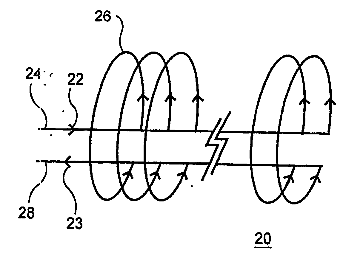
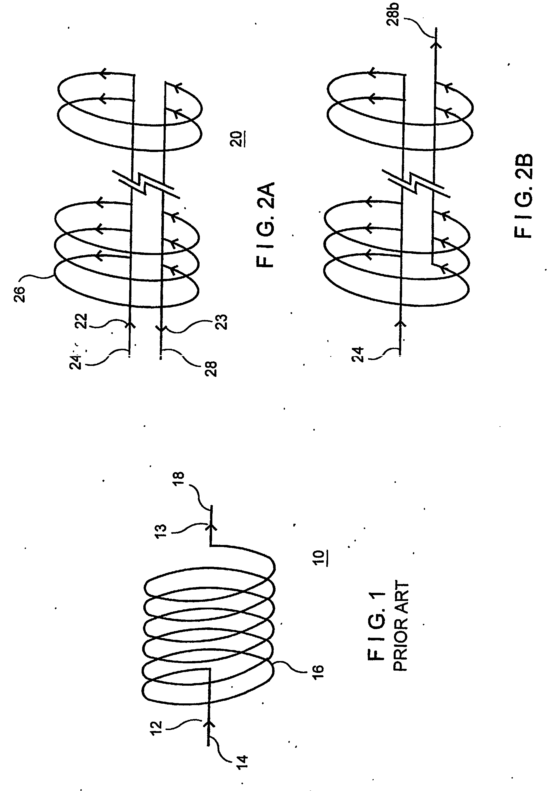
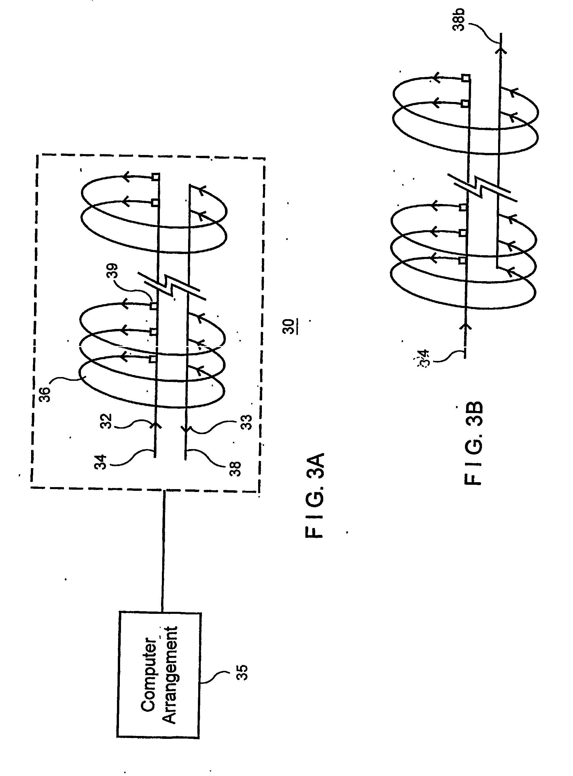
[0011] According to another exemplary embodiment of the present invention, MRI may be performed using the gradient coils that may be designed to produce a strong gradient e.g., only over a relatively restricted region, (e.g., a “ZOnally OptiMized” ZOOM™ gradient coil). The use of such coils may result in a distorted image when implemented with conventional image reconstruction methods to obtain a good resolution, e.g., only in the region of the strong gradient. However, if the portion of the subject which it is desired to image can be positioned within this region, the distortion of further remote regions would likely not pose a practical problem for the image interpretation. Furthermore, since the spatial distribution of the gradient strength is previously known (e.g., can be determined by the geometry of the coil), and thus the resulting image distortion of the further remote regions is known, the images can be corrected for this distortion, and the correct image geometry can be recovered even if the effective local spatial resolution is still non-uniform. The nominal plane of the image may be distorted due to the nonuniformity of the gradient in conjunction with a selective excitation. For a three-dimensional image reconstruction of a slab excitation, the prior knowledge of the gradient configuration can be used to effectively re-sample the reconstructed region into corrected images using flat planes. Due to the fact that a gradient field that is strong only over a restricted region requires less power to generate, and can be switched more rapidly, images may be acquired more rapidly or with a higher resolution than would otherwise be achievable using conventional highly uniform gradient coils.
[0012] Another potential benefit according to the present invention is an effective compression of the region to be reconstructed, which can be produced when using the non-uniform imaging gradient, to reduce the amount of imaging data preferable to be acquired without the potential risk of aliasing: such compression can result in a further decrease of imaging time. Thus, the gradient coil can be used with relatively limited regions of gradient uniformity (e.g., the linear variation of the axial component of the magnetic field) so as to produce a locally-stronger gradient strength than could be achieved with conventional coils, which may be designed to have large regions of gradient uniformity when used in MRI. These coils can be used in conjunction with tailored image processing techniques which are designed to correct for the resulting distortions in image geometry, while retaining the potential for locally greater image resolution.
[0014] According to still another exemplary embodiment of the present invention, a gradient coil can be provided for a generation of a magnetic field gradient that is transverse to the axis of the MRI system, such gradient coil can include at least two sets of approximately parallel arcs with oppositely directed current flows, which can effectively act as a split longitudinally solenoidal coil, with oppositely directed currents in the two fractions. For the arc sets with equal angular extent, this exemplary design of the coil can provide a very homogeneous transverse gradient field across the width of the MM system, which may have advantages over the conventional transverse gradient coil designs. For the arc sets with unequal angular extent, the gradient is likely stronger in the region between the sets, with the potential advantages for an improved performance of local imaging in such region, particularly when viewing the subject area radially off the nominal Z-axis of the MRI machine (i.e., in the X and / or Y direction).

Problems solved by technology

The use of such coils may result in a distorted image when implemented with conventional image reconstruction methods to obtain a good resolution, e.g., only in the region of the strong gradient.
However, if the portion of the subject which it is desired to image can be positioned within this region, the distortion of further remote regions would likely not pose a practical problem for the image interpretation.

Method used


Image

  • Gradient coil arrangement and method for using the same
  • Gradient coil arrangement and method for using the same
  • Gradient coil arrangement and method for using the same

Examples


Embodiment Construction

[0044] Conventional cylindrical MRI systems typically utilize two different kinds of gradient coils: one designed to produce a gradient along the axis of the magnet (i.e., along the nominal “z” direction—“longitudinal”), and another designed to produce a gradient perpendicular to the axis (i.e., along the nominal “x” and / or “y” direction—“transverse”). Combining suitable gradient fields along the x, y, and / or z directions can produce a resultant gradient along any desired combined resultant direction, which can correspondingly be used to produce an image in any desired orientation. It may be convenient to construct gradient coils designed with restricted linear regions, as described herein, to similarly produce primary gradient directions along the nominal x, y, and / or z directions of the MRI system.

[0045] Although conventional gradient coils are generally designed to produce large regions of a homogeneous gradient (i.e., a very linear variation of magnetic field with position alon...


PUM


Abstract

A gradient coil arrangement generates magnetic field gradients across the main magnetic field of a magnetic resonance imaging system and includes a first conductive member, and a second conductive member electrically coupled to the first conductive member, wherein the second conductive member forms a segment that has an approximate shape of an arc when viewed along a direction of extension of the first conductive member.

Description

FIELD OF THE INVENTION [0001] This invention relates generally to magnetic resonance arrangement and method, and more particularly, to gradient coil arrangement for improving magnetic resonance imaging and to methods for providing such arrangements. BACKGROUND INFORMATION [0002] In a magnetic resonance imaging (“MRI”) area, linear magnetic field gradients can be used for spatial encoding. Gradient coils are generally used to produce the linear magnetic field gradients. The gradient coils can be designed to provide an imaging field-of-view that may be fixed in size. In “whole-body” applications, the gradient coil may be designed to produce sufficiently linear or uniform magnetic field gradients over a volume that is larger than e.g., the volume for a dedicated cardiac scanner. As the useful volume is decreased, the stored energy of the gradient coil is generally reduced, which may allow for a higher system performance, and particularly, provide higher peak gradient strengths and fast...

Claims


Application Information

Patent Timeline
IPC IPC(8): H01F3/00
CPCG01R33/385H01F7/202
Inventor AXEL, LEON
Owner NEW YORK UNIV
Learn More