
Process of producing a ceramic matrix composite article and article formed thereby

Active Publication Date: 2007-04-26
GENERAL ELECTRIC CO
View PDF30 Cites 34 Cited by
  • Summary
  • Abstract
  • Description
  • Claims
  • Application Information

AI Technical Summary

Benefits of technology

[0009] The present invention provides a CMC article and a process for producing the CMC article to have an outer barrier layer on its surface that protects the reinforcement material within the article from physical damage during subsequent handling, machining, and surface treatments, and chemical / oxidation damage at high temperature.
[0010] The method of this invention generally entails providing a body containing a ceramic reinforcement material in a matrix material that contains a precursor of a ceramic matrix material. A fraction of the reinforcement material is present and possibly exposed at a surface of the body. A surface layer is then deposited on the surface of the body to define an outermost surface of the body. The surface layer comprises a slurry containing a particulate material, but lacks the reinforcement material of the body. The body and the surface layer thereon are then heated to form a CMC article comprising a ceramic protective layer on a ceramic matrix composite substrate. More particularly, the surface layer is converted to form the ceramic protective layer and the precursor within the body is converted to form the ceramic matrix material in which the ceramic reinforcement material is contained so as to yield the ceramic matrix composite substrate. The ceramic protective layer defines an outermost surface of the CMC article and covers the fraction of the reinforcement material that was originally exposed at the surface of the body. In preferred embodiments of the invention, the surface layer originally deposited on the body may contain chopped or milled carbon fiber or a semicontinuous carbon fiber sheet to inhibit shrinkage cracking during subsequent processing of the body, including its conversion to form the protective layer of the CMC.
[0011] According to a preferred aspect of the invention, the protective layer defining the outermost surface of the CMC article protects the near-surface reinforcement material within the CMC article from handling damage, and also provides a nominal amount of material at the CMC surface that is capable of being machined without damaging the underlying reinforcement material. The latter aspect is especially beneficial for applications where an EBC coating is to be applied to the CMC, in which case a surface roughening treatment is typically performed such as by abrasive grit blasting to promote coating adhesion. Because the protective layer lacks reinforcement material and therefore the weak interface coatings normally applied to reinforcement materials, the protective layer can be substantially harder than the underlying CMC, allowing for a more aggressive grit blasting treatment during clean-up of the article following infiltration or during surface preparation for EBC application. In applications where the CMC will be subjected to high temperature exposures in air or combustion gases, the protective layer provides a barrier that will oxidize and / or volatilize before the fiber-containing material of CMC is subjected to attack, thus extending the time before any mechanical degradation of the CMC article will occur.

Problems solved by technology

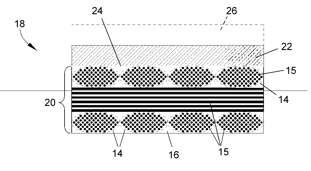
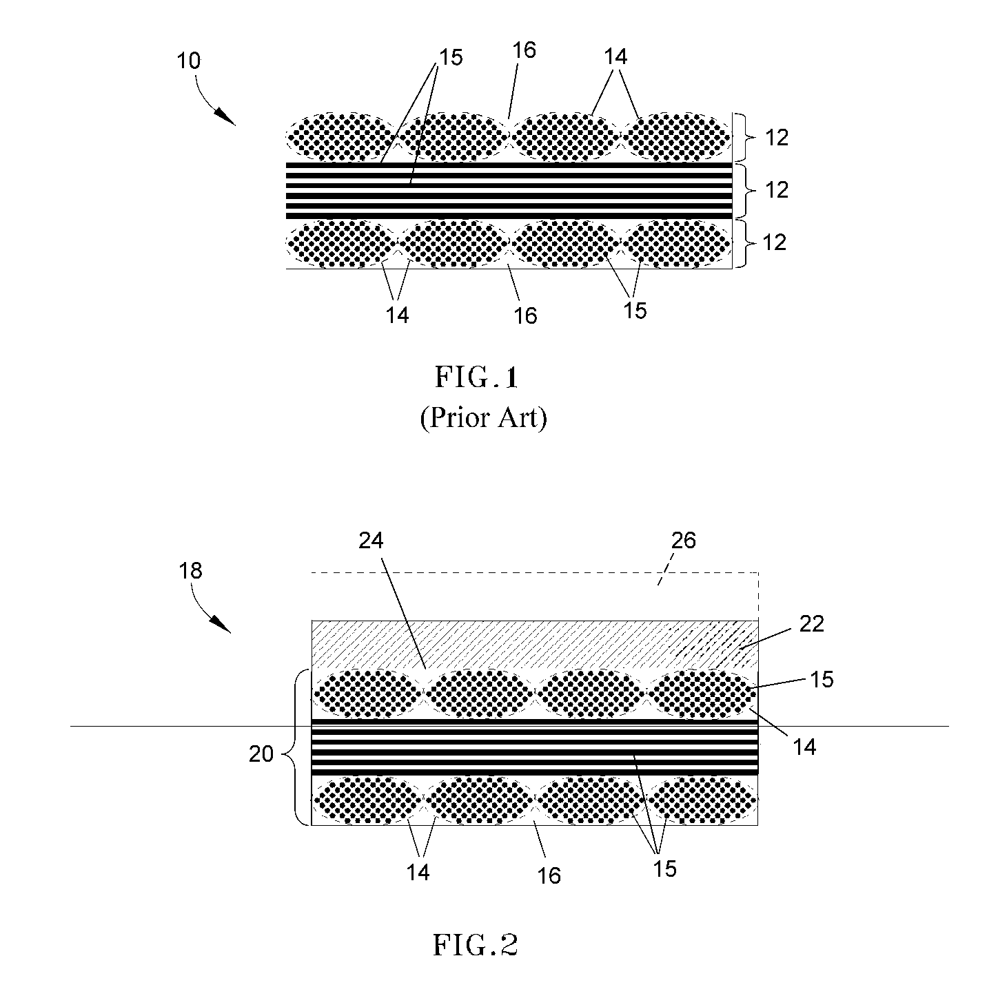
As evident from FIG. 1, such a dispersion inherently places a fraction of the reinforcement material near the surface of the composite where it is susceptible to damage due to handling, machining, surface preparation for subsequent processing steps such as deposition of an environmental barrier coating (EBC), or oxidation attack at high temperature.
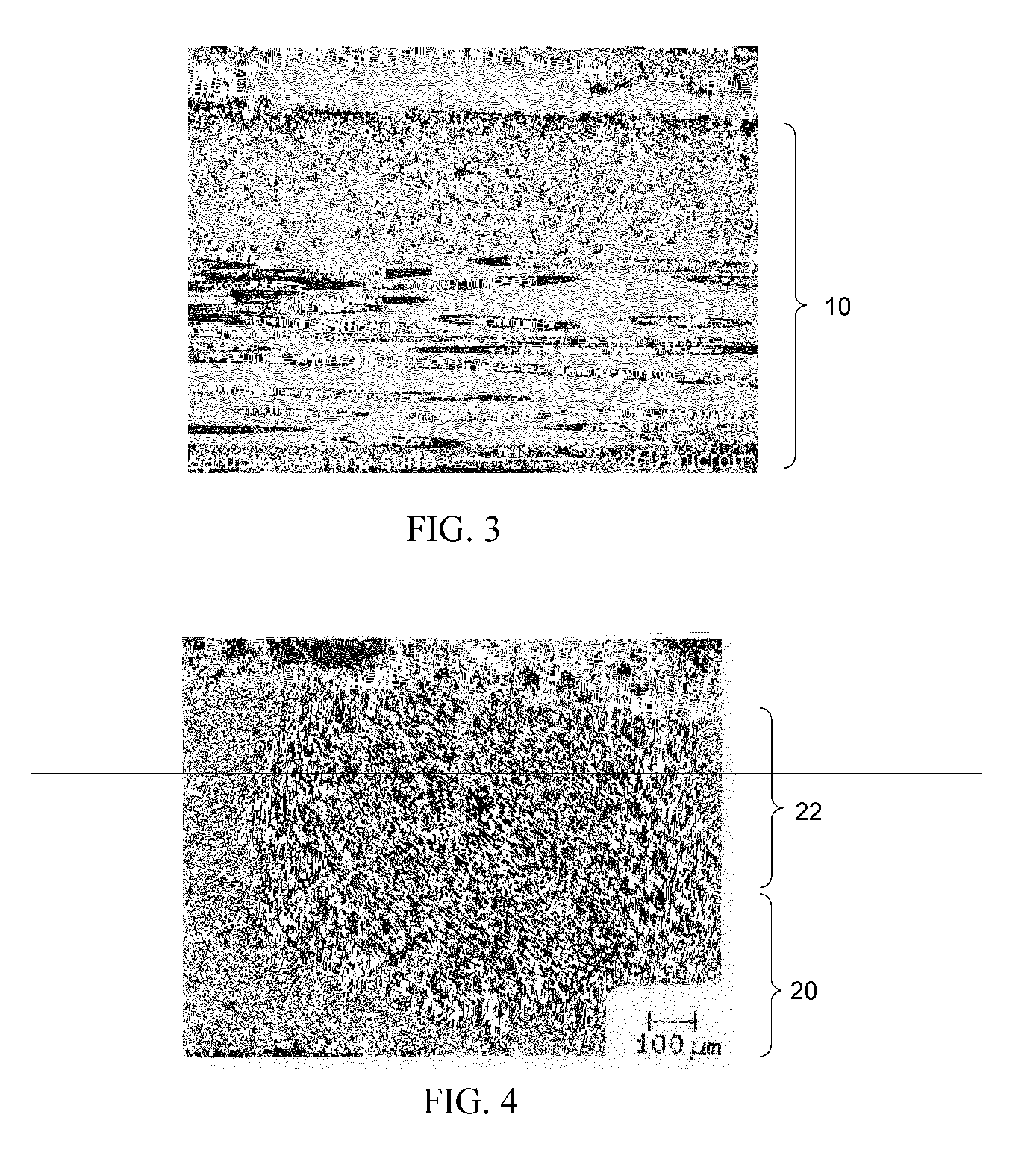
A significant number of reinforcement fibers can be seen relatively close to the surface (within about 0.005 inch (about 125 mm), and therefore susceptible to damage.

Method used


Image

  • Process of producing a ceramic matrix composite article and article formed thereby
  • Process of producing a ceramic matrix composite article and article formed thereby
  • Process of producing a ceramic matrix composite article and article formed thereby

Examples


Embodiment Construction

[0019] The present invention is directed to protecting the outer surface of a CMC article with an outer protective layer. As schematically represented in FIG. 2, a CMC component 18 is shown as having a CMC substrate 20 that is essentially the same as the component 10 of FIG. 1, but over which a protective layer 22 has been formed to define an outermost surface 24 of the component 18. The protective layer 22 lacks any reinforcing material, such as the tows 14 of the underlying substrate 20 of the CMC component 18. Instead, the protective layer 22 is primarily and potentially entirely formed of a ceramic material, which can be formulated to be essentially identical to the ceramic matrix material 16 of the CMC component 18. The manner in which the protective layer 22 is applied to the CMC component 18 can vary depending on the particular process techniques used to produce the component 18. In the particular case of prepreg MI-CMC's of the type represented in FIG. 2, various techniques ...


PUM

PropertyMeasurementUnit
Fractionaaaaaaaaaa
Compositionaaaaaaaaaa
Shrinkageaaaaaaaaaa

Abstract

A CMC article and process for producing the article to have a layer on its surface that protects a reinforcement material within the article from damage. The method entails providing a body containing a ceramic reinforcement material in a matrix material that contains a precursor of a ceramic matrix material. A fraction of the reinforcement material is present and possibly exposed at a surface of the body. The body surface is then provided with a surface layer formed of a slurry containing a particulate material but lacking the reinforcement material of the body. The body and surface layer are heated to form the article by converting the precursor within the body to form the ceramic matrix material in which the reinforcement material is contained, and by converting the surface layer to form the protective layer that covers any fraction of the reinforcement material exposed at the body surface.

Description

[0001] This invention was made with Government support under Agreement No. DE-FC02-92CE41000 awarded by the Department of Energy. The Government has certain rights in the invention.BACKGROUND OF THE INVENTION [0002] The present invention generally relates to ceramic matrix composite (CMC) materials and articles produced therefrom. More particularly, this invention is directed to method of forming a CMC article with a protective outer barrier layer that prevents damage to near-surface reinforcement material within the article. [0003] CMC materials generally comprise a ceramic fiber reinforcement material embedded in a ceramic matrix material. The reinforcement material serves as the load-bearing constituent of the CMC in the event of a matrix crack, while the ceramic matrix protects the reinforcement material, maintains the orientation of its fibers, and serves to dissipate loads to the reinforcement material. Of particular interest to high-temperature applications are silicon-based ...

Claims


Application Information

Patent Timeline
IPC IPC(8): B32B9/00B05D1/18
CPCC04B35/573Y10T428/30C04B38/0032C04B2111/343C04B2235/428C04B2235/5248C04B35/806Y10T428/24983C04B2235/5272C04B2237/368B32B18/00C04B35/62863C04B35/62868C04B35/62871C04B35/62873C04B35/62894C04B35/83C04B2235/3826C04B2235/422C04B2235/5244C04B2235/526C04B2235/5264C04B2235/5268C04B2235/80C04B2237/365C04B2237/38C04B2237/61C04B2237/704C04B35/632C04B35/638C04B2235/614C04B2235/616C04B2237/361C04B2237/363C04B14/386C04B35/565C04B35/80Y10T428/31996
Inventor CORMAN, GREGORY SCOTMCGUIGAN, HENRY CHARLESBRUN, MILIVOJ KONSTANTIN
Owner GENERAL ELECTRIC CO
Learn More