Interconnection structures for semiconductor devices and methods of forming the same

a technology of interconnection structure and semiconductor device, which is applied in the direction of semiconductor device, basic electric element, electrical apparatus, etc., can solve the problems of increasing the resistance of the sheet, affecting the cost of the semiconductor device, and degradation of quality, so as to reduce the resistance of the contact plug, increase the ratio of effective sectional area, and reduce the occurrence of short circuits

Active Publication Date: 2007-04-26
SAMSUNG ELECTRONICS CO LTD
View PDF25 Cites 18 Cited by
  • Summary
  • Abstract
  • Description
  • Claims
  • Application Information

AI Technical Summary

Benefits of technology

[0021] Advantageously, embodiments of the present invention may provide an interconnection structure for a semiconductor device, which can increase the ratio of an effective sectional area of a metal layer and reduce the resistance of a contact plug and a method of forming the same.
[0022] Further, embodiments of the present invention may provide an interconnection structure of a semiconductor device that can prevent and / or reduce the occurrence of short circuits between a contact plug and metal interconnections and a method of forming the same.

Problems solved by technology

Operating frequencies and integration densities are technical factors that may influence the cost of semiconductor devices.
However, such a shrink-down in pitches of interconnections may cause the sheet resistance of the interconnections to increase.
But, when the metal layer 94 directly contacts the impurity regions 40 or the contact plug 60 that contains silicon, it may cause the degradation of quality due to impurity diffusion and abnormal reactions between the metal and the silicon.
However, the necessity for the critical thickness of the barrier metal layer 92 may reduce the ratio of an effective sectional area of the metal in the interconnecting construction 90, which may cause an abrupt increase of the sheet resistance in the interconnecting construction 90.

Method used


Image

  • Interconnection structures for semiconductor devices and methods of forming the same
  • Interconnection structures for semiconductor devices and methods of forming the same
  • Interconnection structures for semiconductor devices and methods of forming the same

Examples


Embodiment Construction

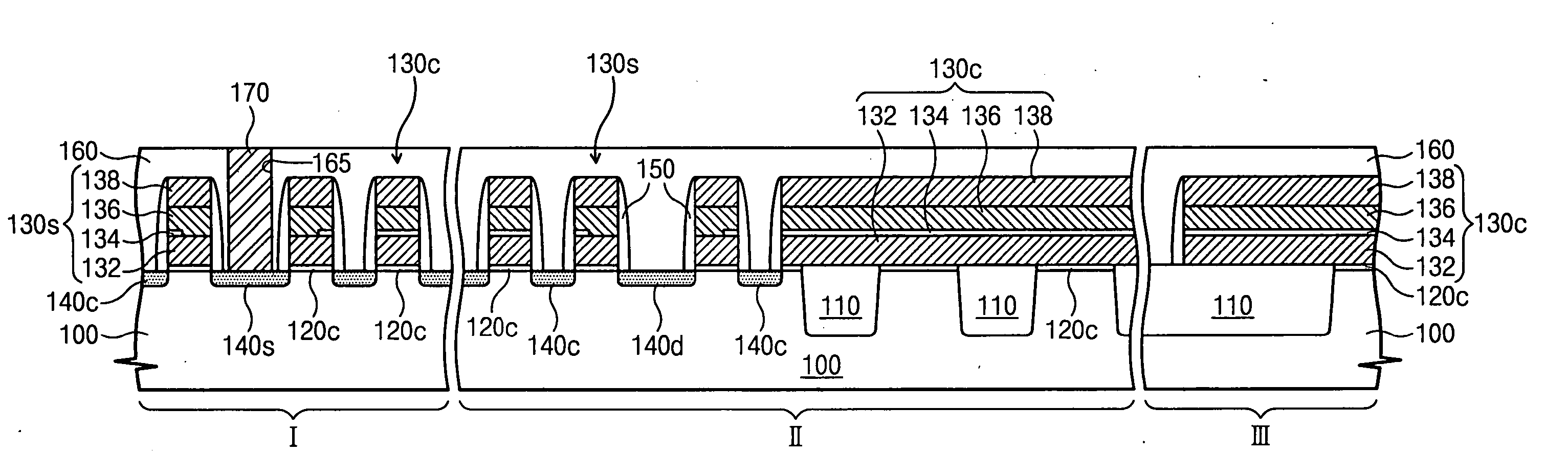
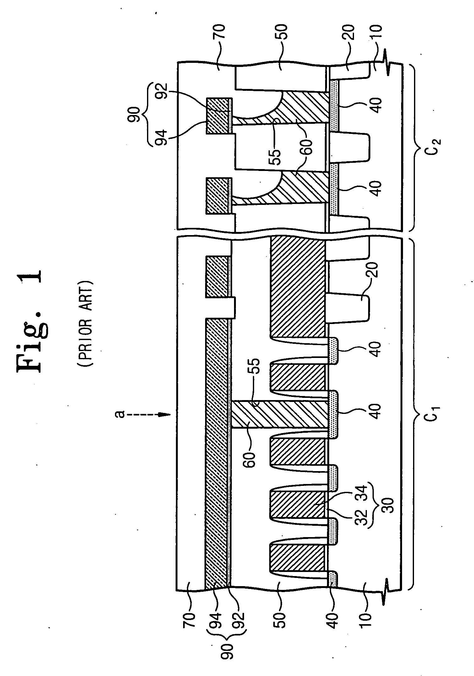
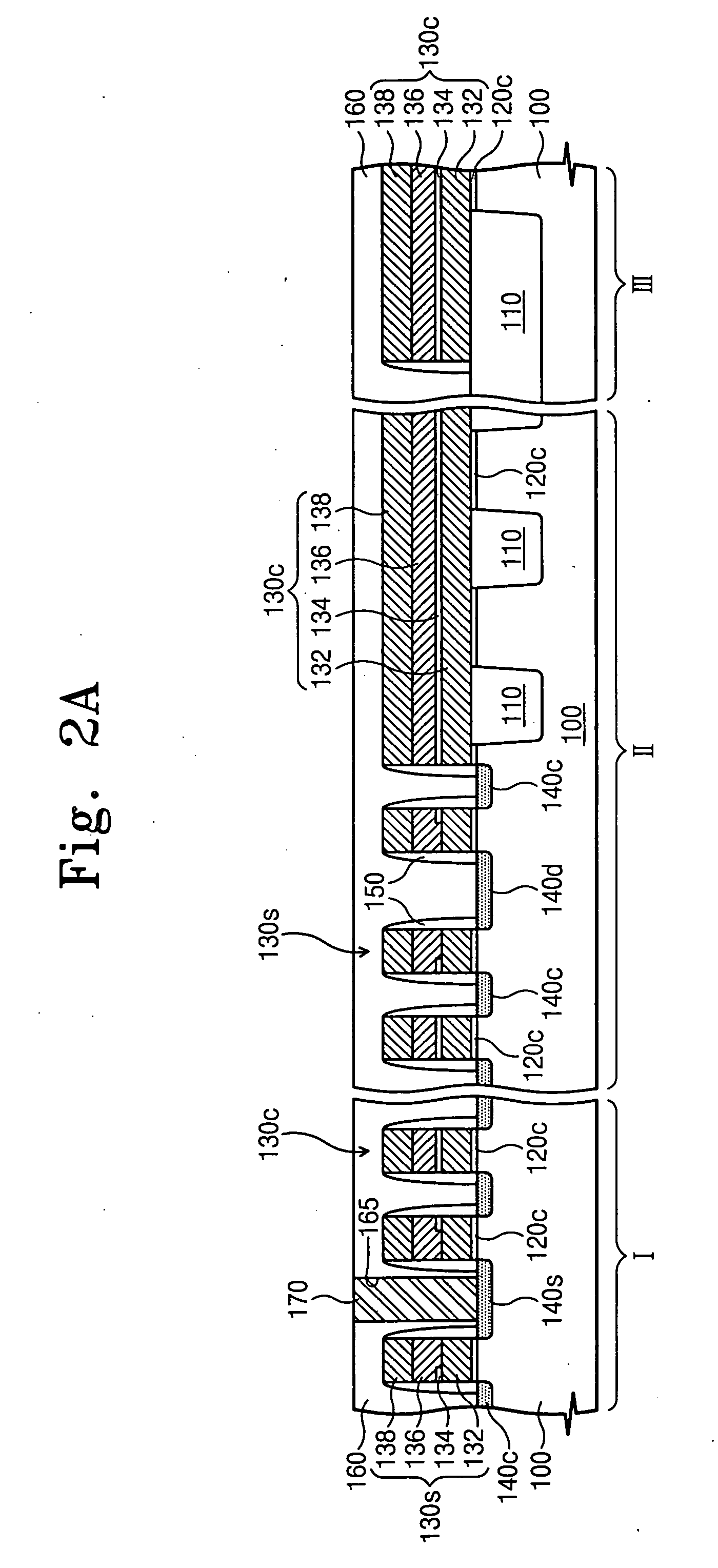
[0036] While the invention is susceptible to various modifications and alternative forms, specific embodiments thereof are shown by way of example in the drawings and will herein be described in detail. It should be understood, however, that there is no intent to limit the invention to the particular forms disclosed, but on the contrary, the invention is to cover all modifications, equivalents, and alternatives falling within the spirit and scope of the invention as defined by the claims. Like reference numbers signify like elements throughout the description of the figures.

[0037] It will be understood that when an element or layer is referred to as being “on,”“connected to,” or “coupled to” another element or layer, it can be directly on, connected, or coupled to the other element or layer or intervening elements or layers may be present. In contrast, when an element is referred to as being “directly on,”“directly connected to,” or “directly coupled to” another element or layer, t...


PUM


Abstract

An interconnection structure includes an inter-level insulation layer disposed on a semiconductor substrate. First contact structures are formed in the inter-level insulation layer. Second contact structures are formed in the inter-level insulation layer and are spaced apart from the first contact structures. First spacers are disposed between the first contact structures and the inter-level insulation layer. Second spacers are disposed between the second contact structures and the inter-level insulation layer. Metal interconnections are disposed on the inter-level insulation layer and connected to the first and second contact structures. The first contact structures include first and second plugs stacked in sequence, the second contact structures include the second plugs, and the first spacers include an upper spacer disposed between the second plug and the inter-level insulation layer.

Description

RELATED APPLICATIONS [0001] This application is a continuation-in-part of U.S. patent application Ser. No. 11 / 022,240 filed Dec. 22, 2004, which claims the benefit of and priority to Korean Patent Application No. 2004-0048119 filed Jun. 25, 2004, the disclosures of which are hereby incorporated herein by reference. This application also claims the benefit of and priority to Korean Patent Application No. 2005-92328 filed Sep. 30, 2005, the disclosure of which is hereby incorporated herein by reference.BACKGROUND OF THE INVENTION [0002] 1. Field of the Invention [0003] The present invention relates generally to integrated circuit devices and methods of forming the same and, more particularly, to interconnection structures for integrated circuit devices and methods of forming the same. [0004] 2. Description of the Related Art [0005] Operating frequencies and integration densities are technical factors that may influence the cost of semiconductor devices. Device manufacturers are genera...

Claims


Application Information

Patent Timeline
Patent Type & Authority Applications(United States)
IPC IPC(8): H01L21/4763
CPCH01L21/76831H01L21/76877H01L27/105H01L27/11526H01L27/11546H10B41/49H10B41/40
Inventor SON, SUK-JOONPARK, JONG-HOKIM, HYUN-SUK
Owner SAMSUNG ELECTRONICS CO LTD
Why Eureka
Try Eureka