Infrastructure repair and geo-stabilization processes

a technology for infrastructure repair and geo-stabilization, applied in the field of polyurethanes, can solve the problems of undesirable and potentially dangerous buildup of heat generated by polyurethane-forming reaction, and achieve the effect of greatly reducing the concern of heat accrual

Inactive Publication Date: 2007-04-26
BAYER MATERIALSCIENCE AG
View PDF13 Cites 30 Cited by
  • Summary
  • Abstract
  • Description
  • Claims
  • Application Information

AI Technical Summary

Benefits of technology

[0012] Accordingly, the present invention provides processes for infrastructure repair and for geo-stabilization with a low-exotherm polyurethane foam, grout or elastomer. The inventive processes involve at least partially filling a cavity in the infrastructure or in the earth with a low-exotherm polyurethane made from at least one polyisocyanate, at least one isocyanate-reactive compound, an organic particulate material capable of absorbing heat, optionally in the presence of one or more chosen from water, surfactants, pigments, catalysts, alkali silicates and fillers and curing the polyurethane foam, grout or elastomer. Because the instant processes utilize low exotherm polyurethane foams, grouts or elastomers, heat accrual is a greatly reduced concern.

Problems solved by technology

A drawback to this procedure is that heat is required to expand foamable plastic materials and is provided by the chemically exothermic polymerization reaction of polymeric isocyanate with polyols and epoxides by basic catalysis which promotes highly exothermic urethane / isocyanurate polymer formation in the presence of suitable blowing agents and surfactants.
Infrastructure repairs and geo-stabilization typically occur in locations where the buildup of heat generated by a polyurethane-forming reaction is not only undesirable, but may be potentially dangerous.

Method used


Image

  • Infrastructure repair and geo-stabilization processes
  • Infrastructure repair and geo-stabilization processes
  • Infrastructure repair and geo-stabilization processes

Examples


examples

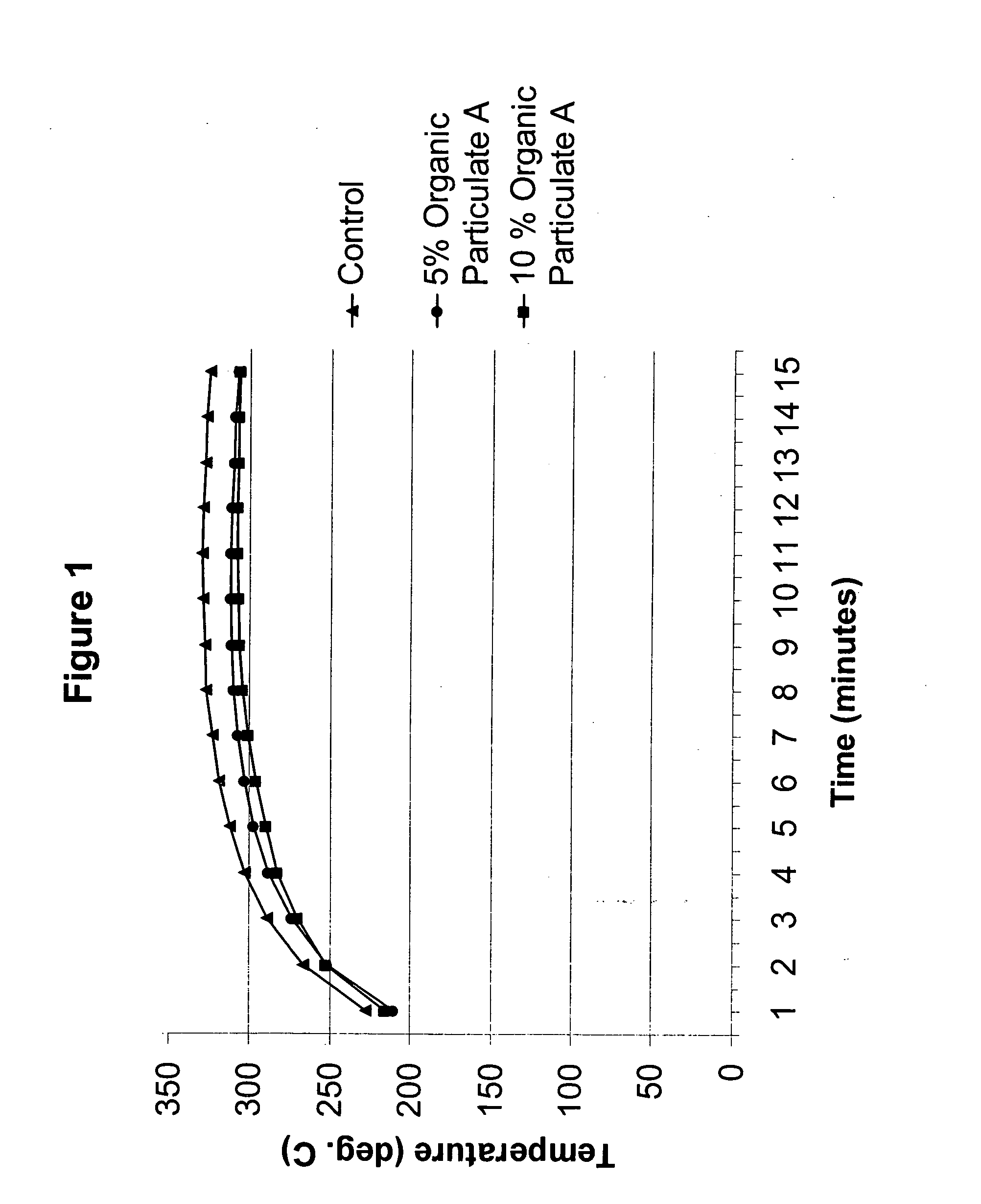
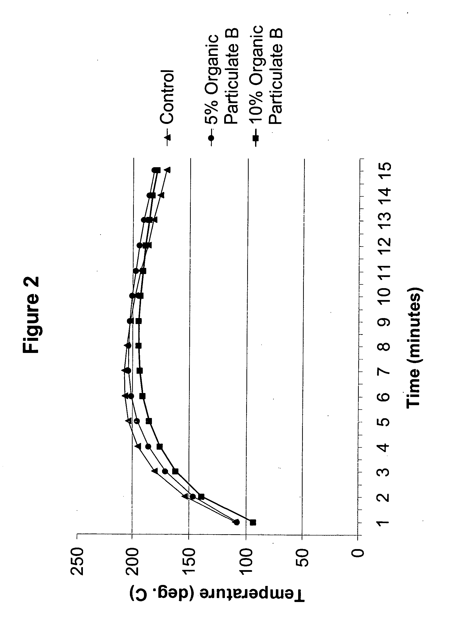
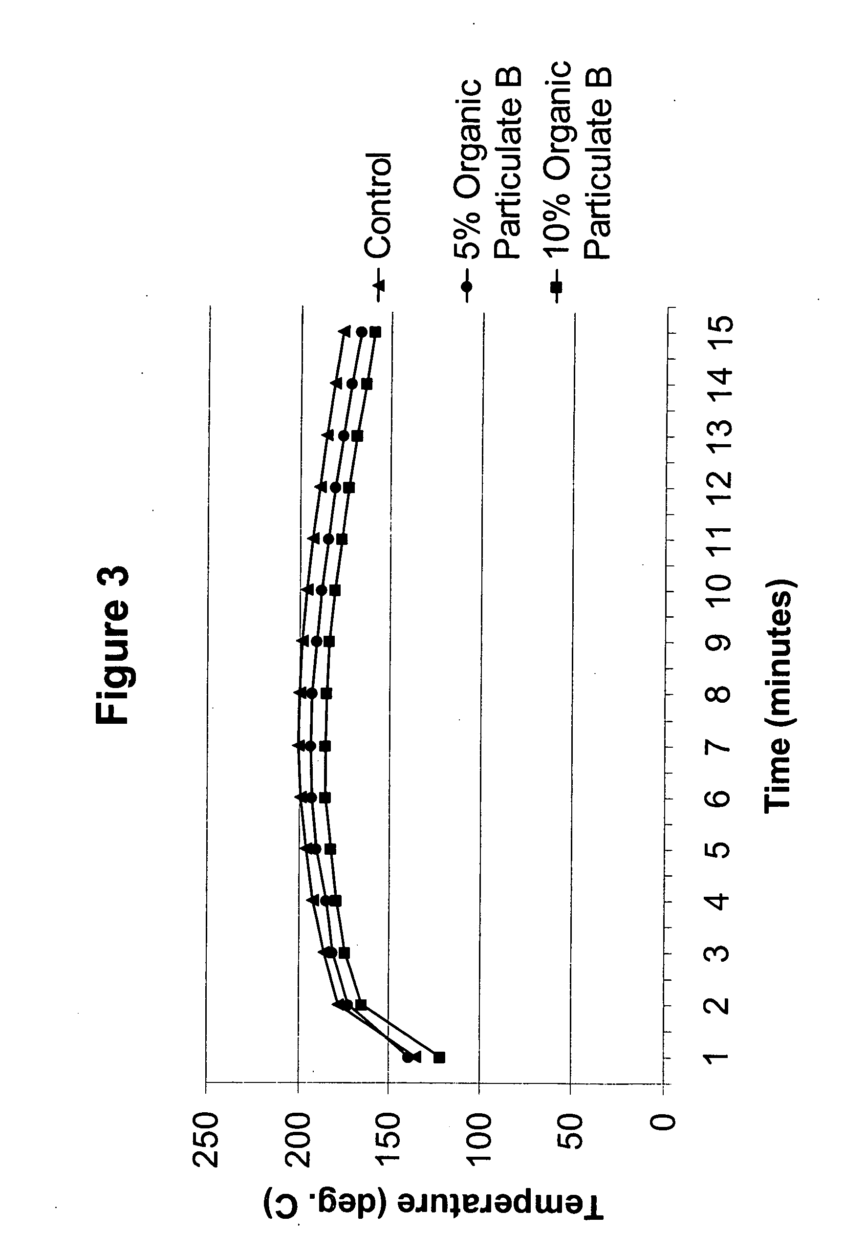
[0060] The present invention is further illustrated, but is not to be limited, by the following examples, in which all quantities given in “parts” and “percents” are understood to be by weight, unless otherwise indicated. The following materials were used in preparing the foams of the examples:

Polyol Aa 43 wt. % solids polymer polyol having a hydroxylnumber of about 18.5, in which the solids are a(63.5%) styrene (36%) acrylonitrile mixturepolymerized in situ in a base polyol having ahydroxyl number of about 36 prepared by KOH-catalyzed alkoxylation of glycerin with a block ofpropylene oxide (80 wt. % of the total oxide)followed by a block of ethylene oxide (20 wt. % ofthe total oxide);Polyol Ba polyether polyol having a molecular weight of6,000 and a functionality of 3.0;Polyol Cpolyether polyols based on ethylene diamine andpropylene oxide (630 OH No.);Polyol Da propoxylated triol based on glycerine having ahydroxyl number of from about 445-495 mgKOH / g;Polyol Ea filled polyol (20...


PUM

PropertyMeasurementUnit
particle sizeaaaaaaaaaa

Abstract

The present invention provides processes for infrastructure repairs and geo-stabilization with a low-exotherm polyurethane foam, grout or elastomer. The inventive process involves at least partially filling a cavity in the infrastructure or earth with a low-exotherm polyurethane foam, grout or elastomer made from at least one polyisocyanate, at least one isocyanate-reactive compound and an organic particulate material capable of absorbing heat, optionally in the presence of one or more chosen from water, surfactants, pigments, catalysts, alkali silicates and fillers and curing the polyurethane foam, grout or elastomer. The inventive processes may improve the repair of buildings, foundations, roads, bridges, highways, sidewalks, tunnels, manholes, sewers, sewage treatment systems, water treatment systems, reservoirs, canals, irrigation ditches, etc.; and in the geo-stabilization of mines, caves, wells, bore-holes, ditches, trenches, pits, cracks, fissures, craters, postholes, potholes, sinkholes, wallows, waterholes and the like.

Description

FIELD OF THE INVENTION [0001] The present invention relates in general to polyurethanes and more specifically to processes for infrastructure repair and for geo-stabilization with a low-exotherm polyurethane foam, grout or elastomer. BACKGROUND OF THE INVENTION [0002] U.S. Pat. No. 4,567,708 issued to Haekkinen, teaches a method for leveling sunken or broken portions of earth-supported floors or slabs involving making at least one hole in the floor and spraying a polyurethane foam between the floor and the underlying earth. The foam creates a mold pressure in the space, which raises the floor. [0003] Andy et al., in U.S. Pat. No. 4,744,700, disclose a method of completely filling mines and underground cavities in such a way as to reinforce the strata and ground thereabove to prevent collapse or subsidence. The method of Andy et al., involves the introduction into mines and cavities of expandable plastic materials which are incorporated into a chemically catalyzed foam reaction and s...

Claims


Application Information

Patent Timeline
Patent Type & Authority Applications(United States)
IPC IPC(8): C08G18/00
CPCC08G18/657C08G2101/0008C08G2101/0016C08G2101/0083C09K8/44E02D3/12E02D35/00E02D37/00C04B2111/00724C04B2111/00732C08G18/4072C08G18/409C08G2110/0008C08G2110/0016C08G2110/0083E04G23/024
Inventor THOMPSON-COLON, JAMES A.JENNY, JACKSUMNER, KENNETH H.
Owner BAYER MATERIALSCIENCE AG
Why Eureka
Try Eureka