Assemblage concrete forms and method for manufacturing thereof

a technology of assemblage and concrete forms, applied in the direction of walls, constructions, building materials handling, etc., can solve the problems of reducing the reliability of buildings, increasing construction costs, and improving construction systems suffering from inefficiency problems, so as to avoid the separation of wall form panels, reduce construction costs, and assembly is easy and fast

Inactive Publication Date: 2007-05-03
ZHU QINJIANG
View PDF5 Cites 24 Cited by
  • Summary
  • Abstract
  • Description
  • Claims
  • Application Information

AI Technical Summary

Benefits of technology

[0028] The concrete wall and the thermal insulation layers are formed simultaneously during the construction process. In this manner, not only a separate construction of thermal insulation layers is eliminated but also the separation of the wall form the panels is avoided, and as a result, the cost of construction is largely reduced.
[0029] The wall form panels are interconnected, in certain embodiments pairwise, by a plurality of jointing pieces, which are then interconnected by transverse and vertical connecting locks. The assembly is easy and fast, the control on the dimensions is accurate, and the integral stability is high, which are beneficial qualities leading to an increase of the overall strength and stability of the structure, a higher resistance to cracking and a greater ability to withstand earthquakes.
[0030] The design of the wall is monolithically integrated, and the production and assembly is modularized. The construction quality and the construction period can be controlled precisely. The factory construction of concrete buildings is realized, and the on-site installation does not require wet conditions.

Problems solved by technology

However, separate steps for producing and installing the insulation layers unnecessarily prolong the construction process resulting in an increase of construction costs and a decrease in the reliability of buildings.
However, despite its advantages, this improved construction system suffers from inefficiency problems because the concrete is poured sectionally and in multiple phases during the construction process.

Method used


Image

  • Assemblage concrete forms and method for manufacturing thereof
  • Assemblage concrete forms and method for manufacturing thereof
  • Assemblage concrete forms and method for manufacturing thereof

Examples


Embodiment Construction

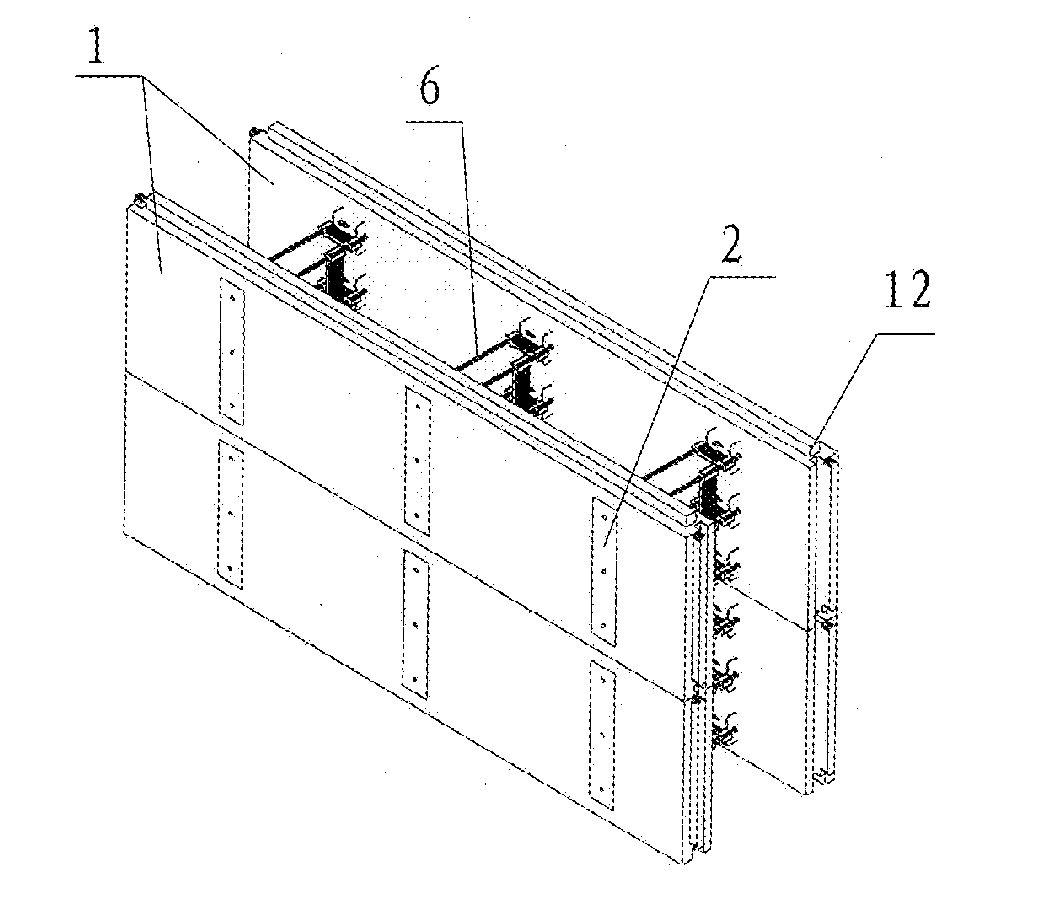
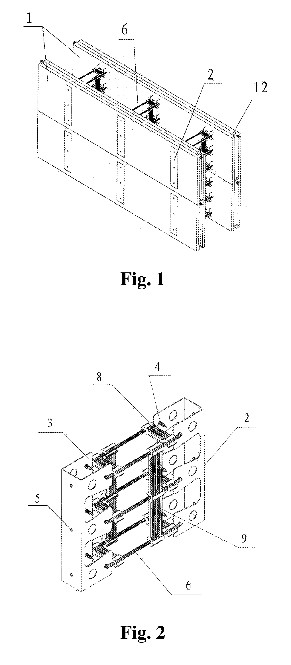
[0066] With reference to FIG. 1, a plurality of steel plates 2 pre-embedded in pre-fabricated form panels 1 are interconnected by a plurality of jointing pieces 6 whereby defining a space for receiving poured concrete between the panels. The peripheral edges of the prefabricated form panels comprise tenons 12 for interconnecting one form panel to another. The vertical joints of the form panels in different layers are staggered with each other (in FIG. 1 two pairs of panels are shown stacked on top of one another). The prefabricated form panel has a length between 900 and 1500 mm, and particularly 1200 mm; a height of between 250 and 600 mm, and particularly 300 mm; and a thickness of between 40 and 60 mm, and particularly 40 mm. The grooves of the transverse and vertical connecting locks are matched with the jointing pieces.

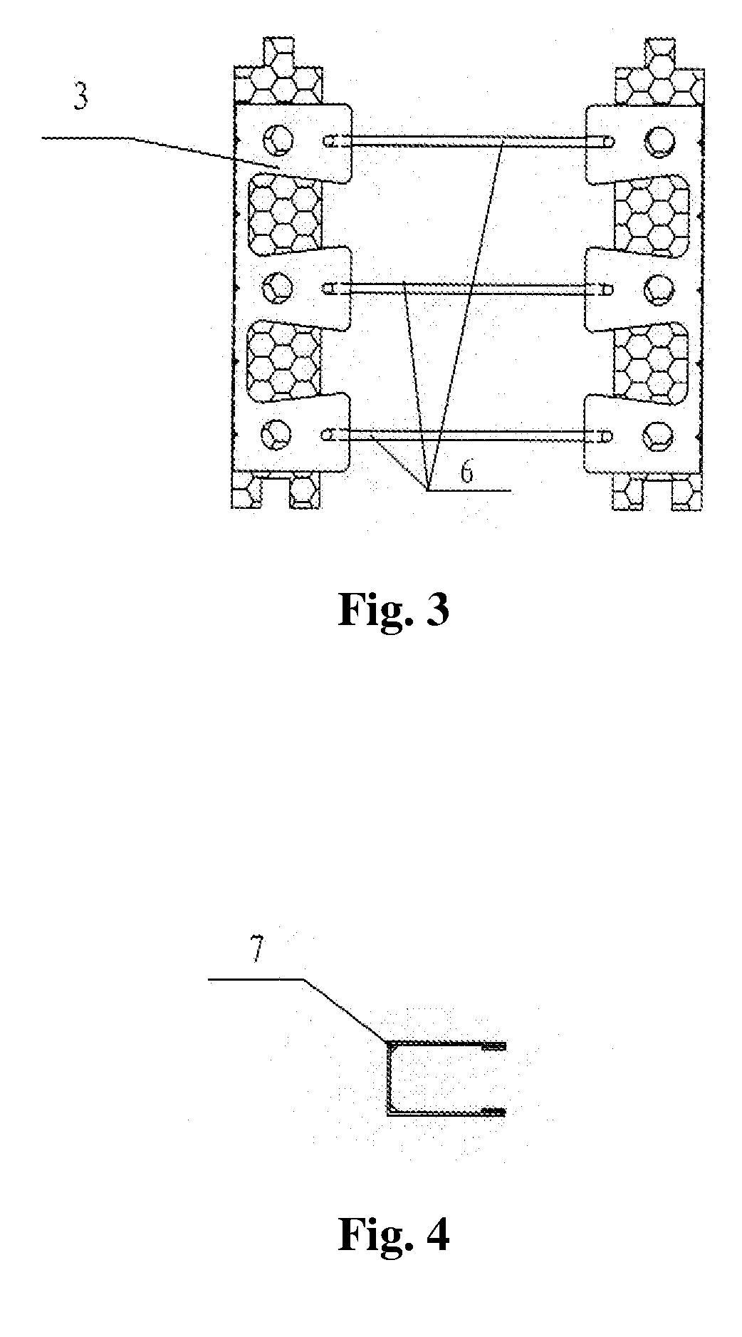
[0067]FIGS. 2-4 illustrate the structure and elements of a steel plate disposed between and jointing two opposed form panels. A steel plate comprises a main boa...


PUM


Abstract

Taught herein is inter alia a concrete wall modulus comprising a concrete-steel wall having one or more steel mesh plates; at least two form panels being physically connected to the concrete-steel wall; a plurality of steel plates; and a plurality of jointing pieces; wherein the form panels are made in part of polystyrene foam; at least two form panels are arranged in parallel to one another; and at least two the form panels are interconnected by a plurality of the jointing pieces by means of the steel plates.

Description

BACKGROUND OF THE INVENTION [0001] 1. Field of the Invention [0002] This invention relates to a composite thermally-insulated concrete wall moduli comprised of pre-fabricated form panels, and a method for manufacturing thereof. [0003] 2. Description of the Related Art [0004] Higher energy costs and worries about the environmental impact of global warming have lead to an overall increase in construction of energy-saving buildings, and specifically to the development of various energy-saving technologies for building construction, with the emphasis on the improvement of the thermal insulating properties of walls, roofs, doors and windows. [0005] Conventional buildings are constructed using the structure-first-thermal-insulation-second-and-decoration-last approach, wherein external and internal multi-layered insulations are often employed. However, separate steps for producing and installing the insulation layers unnecessarily prolong the construction process resulting in an increase o...

Claims


Application Information

Patent Timeline
Patent Type & Authority Applications(United States)
IPC IPC(8): E04B2/00
CPCE04B1/161E04B2/8647E04B2002/867
Inventor ZHU, QINJIANG
Owner ZHU QINJIANG
Why Eureka
Try Eureka