
Method for cache correction using functional tests translated to fuse repair

a functional test and cache correction technology, applied in error detection/correction, instruments, computing, etc., can solve problems such as inability to determine the proper data stream, eccs cannot be used to detect and correct single-bit, and given cache block may contain an incorrect valu

Inactive Publication Date: 2007-05-03
IBM CORP
View PDF8 Cites 19 Cited by
  • Summary
  • Abstract
  • Description
  • Claims
  • Application Information

AI Technical Summary

Benefits of technology

[0011] It is therefore one object of the present invention to provide an improved method of handling errors in a cache memory.
[0012] It is another object of the present invention to provide such a method which corrects hard errors that might otherwise arise in the field after factory testing.
[0013] It is yet another object of the present invention to provide an improved method of identifying potential repairable failures in a computer storage array.

Problems solved by technology

A bit in a given cache block may contain an incorrect value either due to a soft error (such as stray radiation or electrostatic discharge) or to a hard error (a defective cell).
Some ECCs can only be used to detect and correct single-bit errors, i.e., if two or more bits in a particular block are invalid, then the ECC might not be able to determine what the proper data stream should actually be, but at least the failure can be detected.
These latter errors are costly to correct, but the design tradeoff is to halt the machine when double-bit (uncorrectable) errors occur.
These larger, dense arrays decrease the reliability of the overall chip / system due to increased chances of defects that occur in manufacturing or after deployment in the field.
While soft errors (i.e., intermittent faults) are easily corrected using ECC circuits that repair and re-write the data in the directory, this technique does not solve hard faults that occur over time, i.e., after wafer-level or BIST testing, particularly end-of-life defects.

Method used


Image

  • Method for cache correction using functional tests translated to fuse repair
  • Method for cache correction using functional tests translated to fuse repair
  • Method for cache correction using functional tests translated to fuse repair

Examples


Embodiment Construction

)

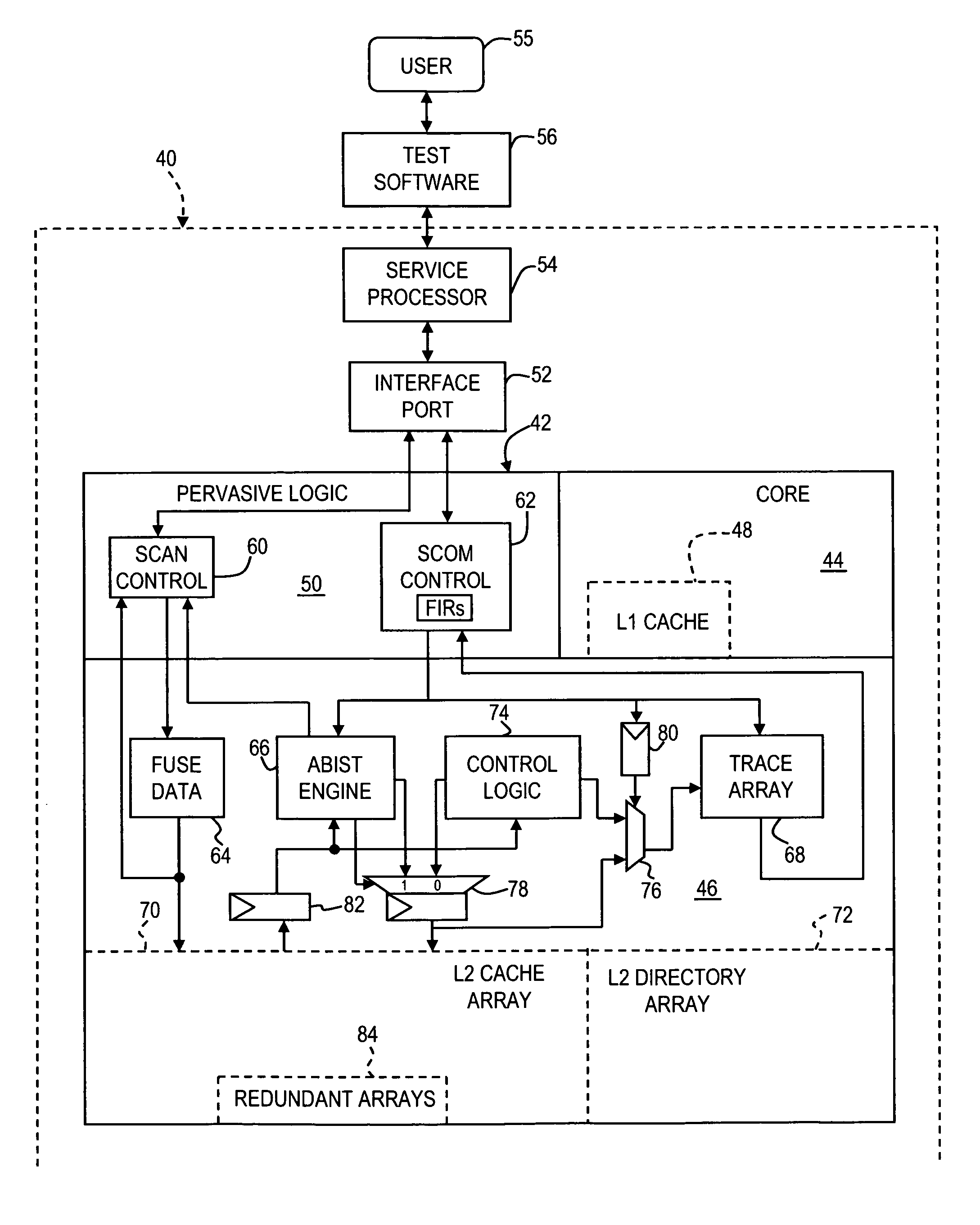
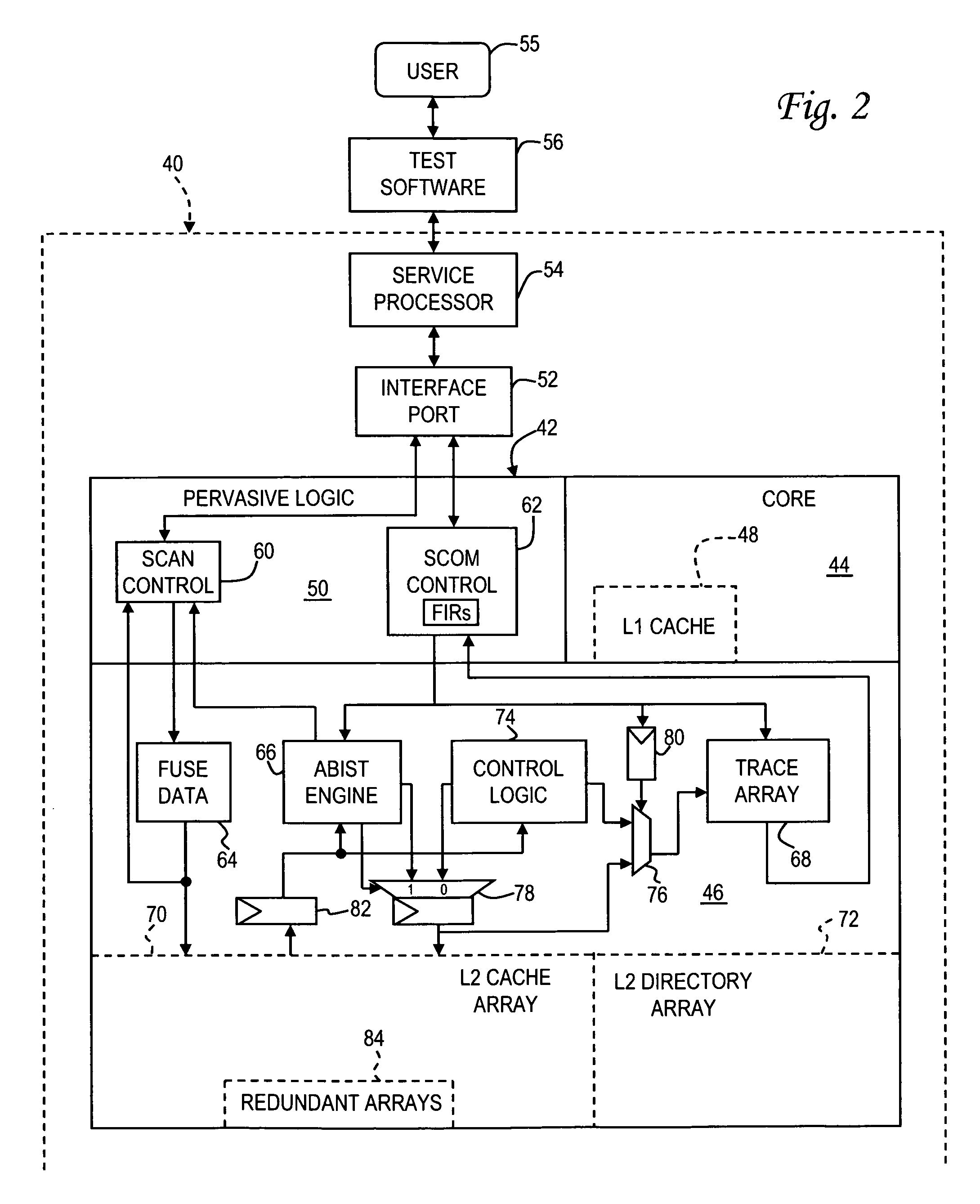
[0021] With reference now to the figures, and in particular with reference to FIG. 2, there is depicted one embodiment 40 of a computer system constructed in accordance with the present invention. Computer system 40 includes a processing unit 42 having one or more processor cores 44 and a second level (L2) cache 46. Each processor core has its own L1 (on-board) cache 48. Computer system 40 may include additional features not shown in FIG. 2, such as system memory, one or more interconnect buses, and peripheral devices.

[0022] Computer system 40 also includes pervasive logic 50 which is used to load values into internal latches and access internal registers of various components in system 40. Pervasive logic 50 may be connected to an interface (JTAG) port 52 which in turn is connected to a service processor 54. JTAG port 52 complies with the Institute of Electrical and Electronics Engineers (IEEE) standard 1149.1 pertaining to a test access port and boundary-scan architecture. JTAG ...


PUM


Abstract

A method of correcting defects in a storage array of a microprocessor, such as a cache memory, by operating the microprocessor to carry out a functional test procedure which utilizes cache memory, collecting fault data in a trace array during the functional test procedure, identifying a location of the defect in the cache memory using the fault data, and repairing the defect by setting a fuse to reroute access requests for the location to a redundant array. The fault data may include an error syndrome and a failing address. The functional test procedure creates random cache access sequences that cause varying loads of traffic in the cache memory using a test pattern based on a random seed. The functional test procedure may be carried out after completion of a nonfunctional, built-in self test of the microprocessor which sets some of the fuses.

Description

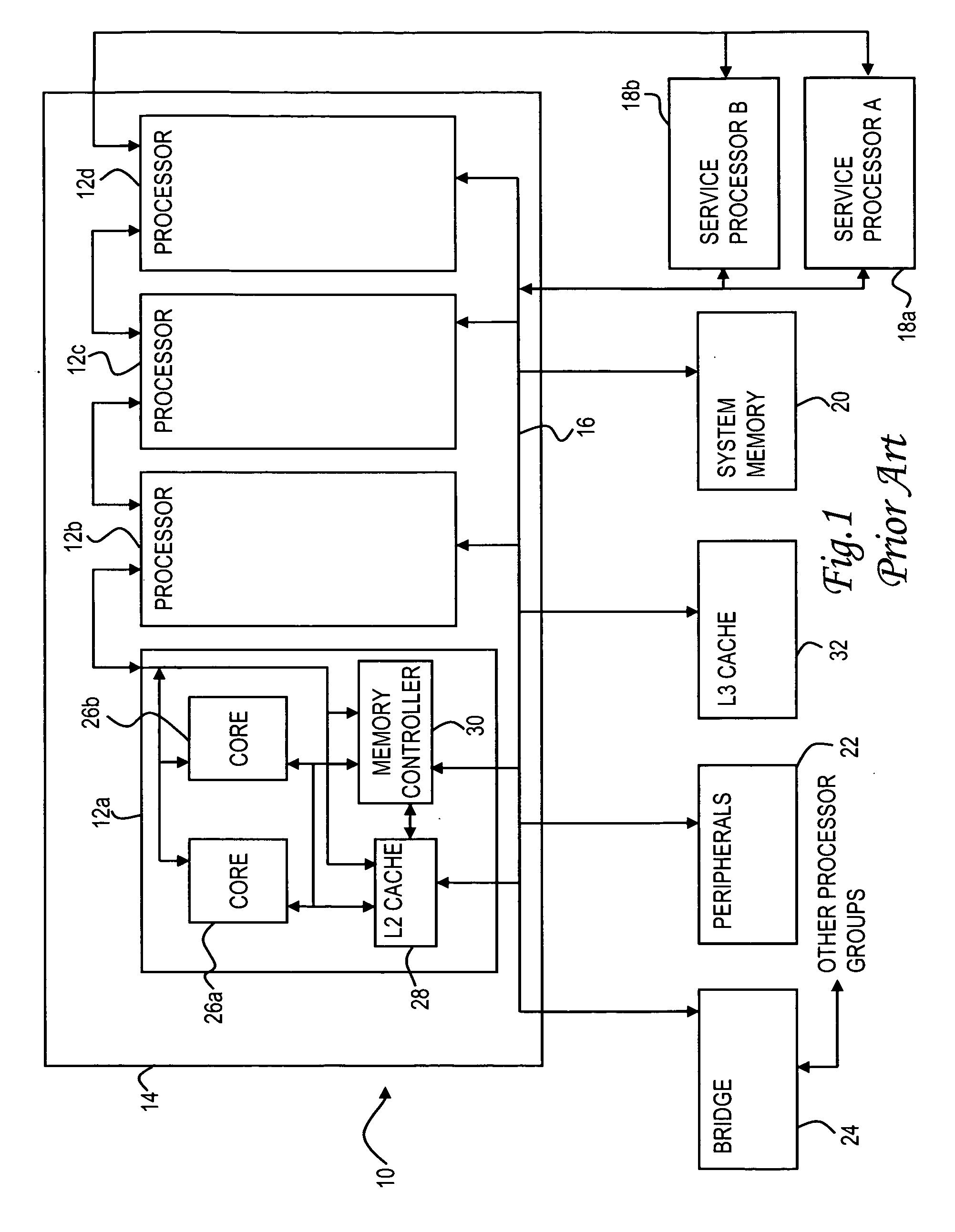
BACKGROUND OF THE INVENTION [0001] 1. Field of the Invention [0002] The present invention generally relates to computer systems, and more particularly to a method of handling defects in a storage array such as a cache memory of a computer system. [0003] 2. Description of the Related Art [0004] The basic structure of a conventional symmetric multi-processor computer system 10 is shown in FIG. 1. Computer system 10 has one or more processing units arranged in one or more processor groups; in the depicted system, there are four processing units 12a, 12b, 12c and 12d in processor group 14. The processing units communicate with other components of system 10 via a system or fabric bus 16. Fabric bus 16 is connected to one or more service processors 18a, 18b, a system memory device 20, and various peripheral devices 22. A processor bridge 24 can optionally be used to interconnect additional processor groups. System 10 may also include firmware (not shown) which stores the system's basic in...

Claims


Application Information

Patent Timeline
IPC IPC(8): G06F11/00
CPCG06F11/1474G06F11/2236
Inventor LOCKWOOD, WALTER R.PENNINGTON, RYAN J.SHEN, HUGHWRIGHT, KENNETH L.
Owner IBM CORP
Learn More