
Soldering method and apparatus

a technology of soldering method and apparatus, which is applied in the direction of soldering apparatus, sustainable manufacturing/processing, and final product manufacturing, etc., can solve the problems of deteriorating the reliability of solder bonding, affecting the reliability of soldering, and not irradiating the laser beam, so as to improve the wettability of the solder for the bonding pad, improve the reliability of soldering, and ensure the effect of bonding

Inactive Publication Date: 2007-05-10
SAE MAGNETICS (HK) LTD
View PDF6 Cites 17 Cited by
  • Summary
  • Abstract
  • Description
  • Claims
  • Application Information

AI Technical Summary

Benefits of technology

The present invention provides a method and apparatus for soldering that improves the inconveniences of conventional cases. The method involves heating the bonding pads on the surfaces of the targets to be bonded with solder using heating beams, followed by melting the solder and attaching it to the bonding pads by irradiating the heating beams. The heating beams are irradiated simultaneously to multiple bonding pads, and the intensity of the heating beams can be adjusted based on the positions of the bonding pads. This method improves the reliability of soldering and allows for a simpler and more efficient soldering process.

Problems solved by technology

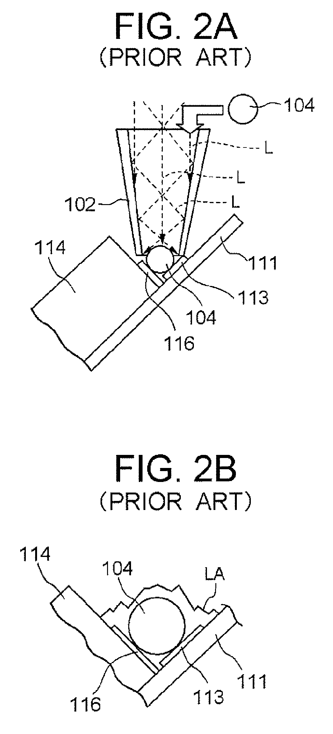
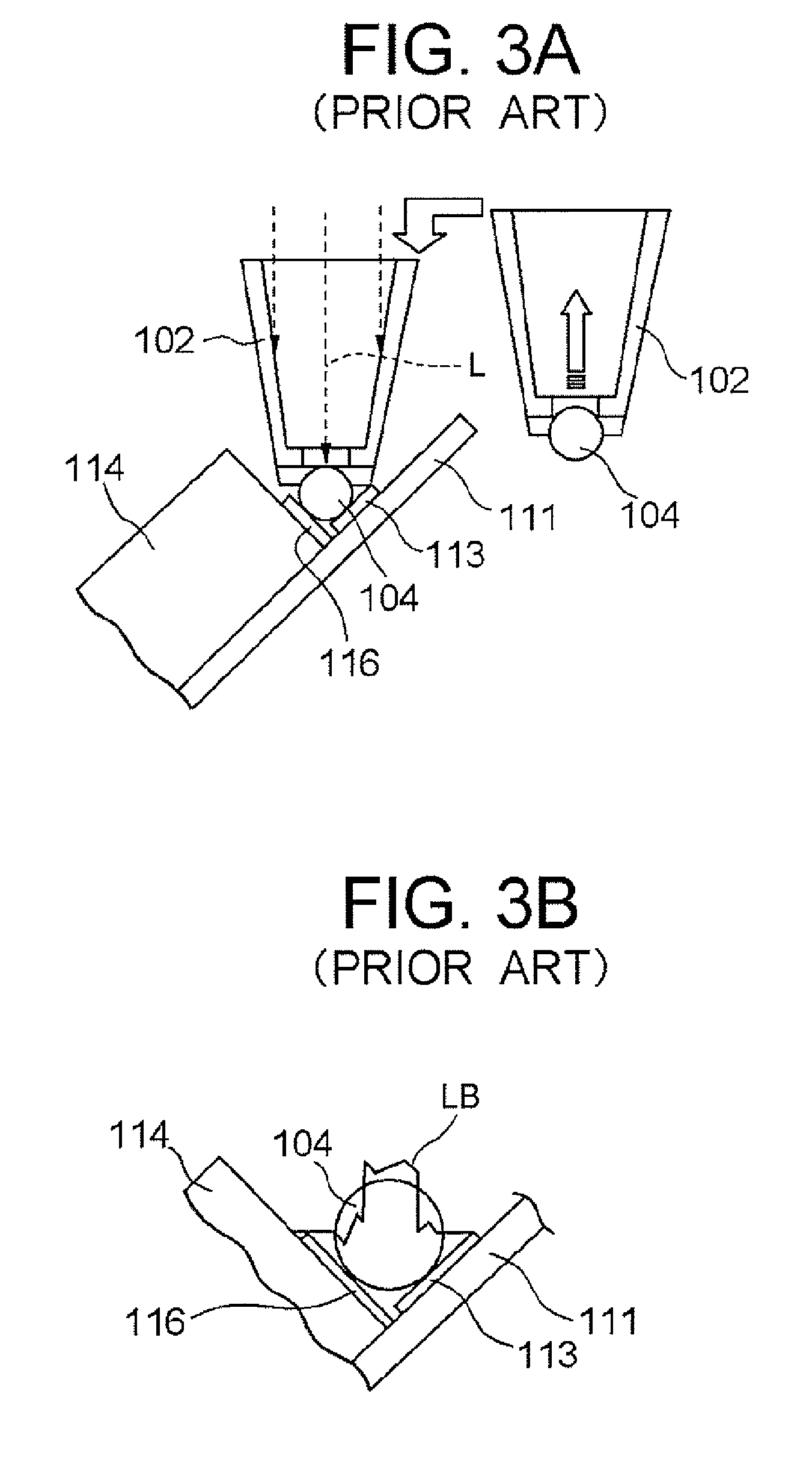
Furthermore, in the case of FIG. 3A where the opening diameter of the nozzle is formed smaller than the solder ball 104, the laser beams L are irradiated only to the solder ball, which causes such an inconvenience that the laser beams are not irradiated at all to the bonding pads.
Thus, the temperatures of the bonding pads 113 and 116 are not sufficiently increased and the wettability of the molten solder is deteriorated, which may deteriorate the reliability of the solder bonding, e.g. generating connection failure.
This may cause damaging of the electronic components by the heat of soldering.
Therefore, heating of the solder by the laser or the like has conventionally been restricted to a short time.
However, when heating of solder is restricted to a short time, fusion of the solder becomes insufficient due to the short-heating time.
Thus, as noted below, stable soldering cannot be achieved.
Therefore, the solder 140 in the junction area is divided into the gold-tin alloy and the tin alloy, so that solder cracks are likely to be generated at the boundary surface between each alloy.
In addition, solder separation is likely to be generated since the strength of the tin alloy is weak.
As a result, reliability of soldering is decreased.

Method used


Image

  • Soldering method and apparatus
  • Soldering method and apparatus
  • Soldering method and apparatus

Examples


first embodiment

[0070] A first embodiment of the present invention will be described by referring to FIG. 6-FIG. 10. FIG. 6 is a schematic view for showing the structure of a soldering apparatus. FIG. 7-FIG. 8 are illustrations for describing the state at the time of soldering. FIG. 9 is a crystallographic picture for showing the state of the solder after soldering is performed. FIG. 10 is a flowchart for describing actions at the t-me of soldering performed by the soldering apparatus.

[Structure]

[0071] A soldering apparatus 20 according to this embodiment fabricates a head gimbal assembly 1 by solder-bonding a magnetic head slider 14(bonding target) to a suspension 11 (bonding target). As shown in FIG. 6A, the soldering apparatus 20 comprises a laser irradiator (irradiation device) having a nozzle 2 for outputting laser beams (heating beams) to heat the solder, and a controller 3 (controlling device) for controlling the action of the entire apparatus. In the followings, each structure will be des...

second embodiment

[0090] Next, a second embodiment of the present invention will be described by referring to FIG. 11. The soldering apparatus 20 of this embodiment has almost the same structure as that of the first embodiment, except that the control of the laser beam irradiation by the controller 3 is different. In the followings, this point will be described in detail. Other structures are same as those of the first embodiment, so that the descriptions thereof are omitted.

[Structure]

[0091] Before the solder is melted, the controller 3 (controlling device) according to this embodiment controls to perform irradiation by setting the intensity of the laser beams weaker than that of the laser beams irradiated when melting the solder as will be described later. That is, there are irradiated the laser beams with low intensity with which the sclder hall 4 is not melted within a time set in advance from the start of the laser irradiation. Further, the controller 3 controls to irradiate the laser beams wi...

third embodiment

[0096] Next, a third embodiment of the present invention will be described by referring to FIG. 12-FIG. 13. FIG. 12 illustrates the structure of the soldering apparatus according to this embodiment, and FIG. 13 is a flowchart for showing the operation thereof.

[Structure]

[0097] As shown in FIG. 12A and FIG. 12B, the soldering apparatus according to this embodiment performs irradiation of the laser beams L1, L2, L3 while holding the solder ball 4 at the tip part 21 of the nozzle 2, and the solder 40 melted by the laser irradiation is discharged onto the bonding pads 13, 16 positioned in the junction area (see an arrow with dotted line in FIG. 12A) to attach the solder 40 on the bonding pad 13, 16 for achieving soldering.

[0098] The structure of the soldering apparatus will be described in more detail. As shown in FIG. 12A, the shape of the nozzle 2 is the same as that described above, and the solder ball 4 is held at the solder irradiation hole 22 among the laser output ports formed...


PUM

PropertyMeasurementUnit
timeaaaaaaaaaa
diameteraaaaaaaaaa
timeaaaaaaaaaa

Abstract

It is a soldering method for bonding, by solder, each bonding pad formed on respective bonding targets to be bonded to each other. The method comprises the steps of: a pad heating step for irradiating heating beams while the solder is placed on irradiation paths of the heating beams in such a manner that each bonding pad is heated before the solder is melted; and a solder melting step for melting the solder by the heating beams to be attached on each bonding pad, wherein the heating beams are irradiated almost simultaneously in the pad heating step and the solder melting step, and a molten solder heating step is provided thereafter for further heating the molten solder on the bonding pads by the heating beams.

Description

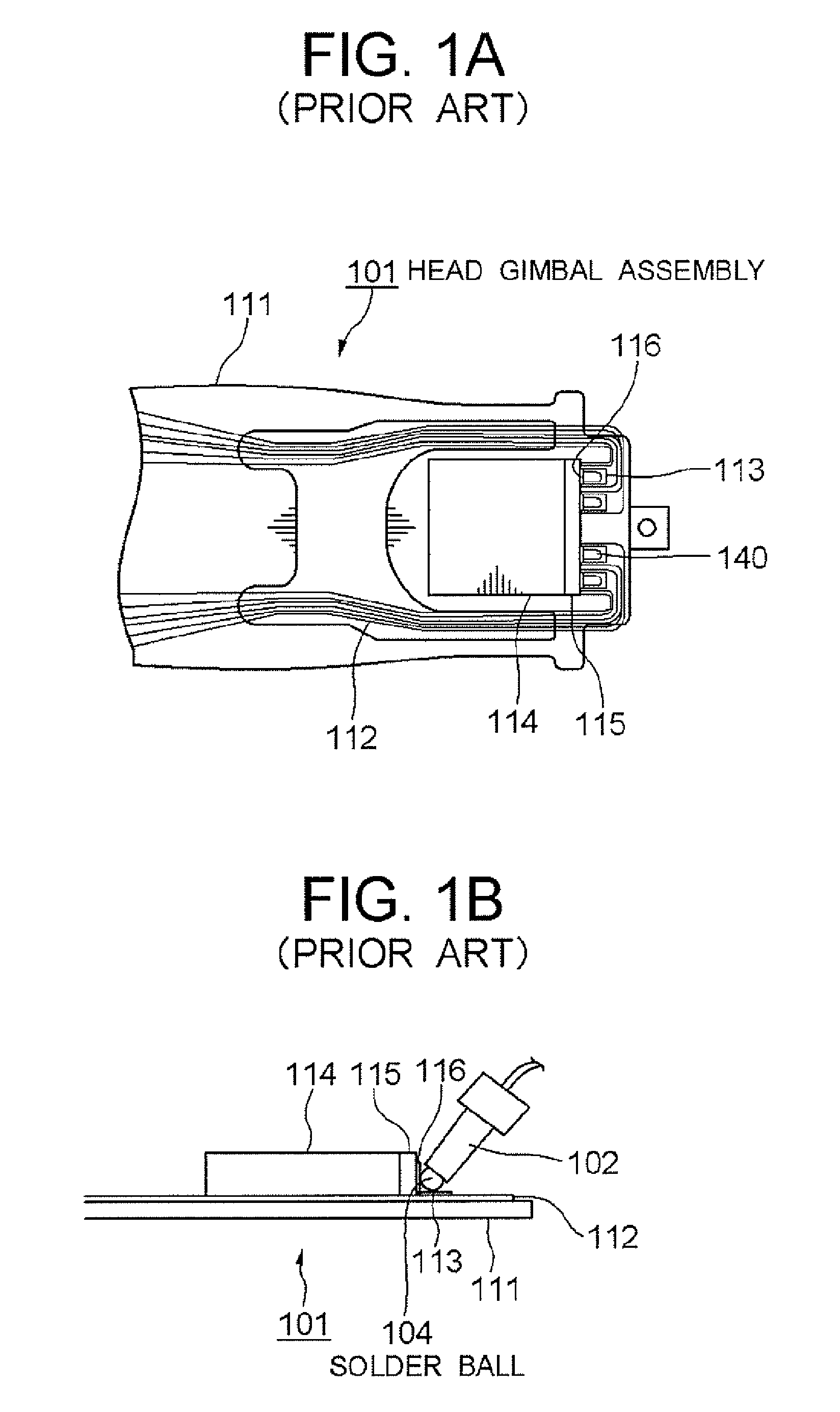
BACKGROUND OF THE INVENTION [0001] 1. Field of the Invention [0002] The present invention relates to a soldering method and an apparatus thereof and, more particularly, to a soldering method and apparatus for bonding, by soldering, each bonding pad formed on respective bonding targets which are to be bonded to each other. [0003] 2. Description of the Related Art [0004] Soldering is to perform bonding through heating and melting solder on a bonding pad surface where a gold-plated layer is formed, so that the solder and the gold on the bonding pad surface are fused to form a gold-tin alloy. It is used as a means for bonding electronic components to a substrate and the like, for example. By way of example, as shown in FIG. 1A, it is used when fabricating a magnetic head assembly 101 by soldering a magnetic head slider 114 having a magnetic head element 115 as an electronic component to a suspension 11 to which a flexible printed circuit 112 is integrated. [0005] A typical method for so...

Claims


Application Information

Patent Timeline
Patent Type & Authority Applications(United States)
IPC IPC(8): A47J36/02
CPCB23K1/0056B23K3/0623H05K3/3442H05K3/3478H05K3/3494H05K2201/10727H05K2203/041H05K2203/107H01L2224/11003H01L2224/742H01L2224/05573Y02P70/50
Inventor FUKAYA, HIROSHIYAMAGUCHI, SATOSHI
Owner SAE MAGNETICS (HK) LTD
Learn More