Process and system for printing images on absorptive surfaces

a technology of absorption surface and printing process, applied in the field of printing, can solve the problems of rotogravure printing being less suitable for multicolor images and designs on textiles, one of the most expensive techniques, and only partially meeting the requirements of the above-mentioned techniques

Inactive Publication Date: 2007-05-10
KORNIT DIGITAL LTD
View PDF107 Cites 92 Cited by
  • Summary
  • Abstract
  • Description
  • Claims
  • Application Information

AI Technical Summary

Benefits of technology

[0041] The present inventors have now surprisingly found that by wetting a surface onto which an image is to be printed with a wetting composition that interfere with the engagement of the ink with the surface and thus temporarily modify the ...

Problems solved by technology

The ever growing demand for new and stimulating garment and fabric fashion, one of the greatest commercial markets, challenges cutting edge technology to innovate in areas such as fiber materials, weaving and threading, cloth fabrication, dying and post treatment of textile fabrics.
There are several technical and logistic challenges on the way to accomplishing the goal of high-resolution, high-definition art printing unique to textile printing, especially when the fabric is used for a garment.
However, the requirements set forth above are only partially met with these techniques, as is discussed in detail hereinbelow.
Rotogravure printing is ideal for long run high fidelity half tone printing at high speeds, yet it is one of the most expensive techniques due to the high cost of plate cylinder production.
As other printing mold block techniques, rotogravure printing is less suitable for complex, multicolor images and designs on textile.
Its main disadvantage is its incapacity to create a high definition multicolor image on textile.
Upon cooling, the ink solidifies to various degrees of hardness, and thus a printed image that gives an unpleasant feel is formed.
Aqueous-based inks tend to absorb in the fabric, and smudge, and thus oftentimes a blurred image is formed.
This technique is suitable for simple, one or two color, graphics but is ineffective for more complex and photorealistic prints.
In any event, as mentioned above, this technique typically results in a blur image and/or an image with an unpleasant feeling.
The resulting image is vivid and of high definition, but tends to crack upon usage, has an unpleasant feel and seals the fabric from “breathing”.
However, the process is limited only to polyester bland fabrics and, furthermore, the use of special inks and the extra step of sublimation render this technique highly expensive.
The presently used printing methods detailed above therefore fail to meet contemporary demands of the fashion industry by failing to produce high-resolution and photorealistic multicolor images.
The disadvantages of these methods generally result from the multi-step processes that are involved, the cost and time-consuming pre-treatment of the fabrics, and, above all, the mediocre results obtained the...

Method used


Image

  • Process and system for printing images on absorptive surfaces
  • Process and system for printing images on absorptive surfaces
  • Process and system for printing images on absorptive surfaces

Examples


example 1

[0435] Non-aqueous solvent-based ink compositions, having the four basic formulations of cyan, magenta, yellow and black colors (CMYK), were used.

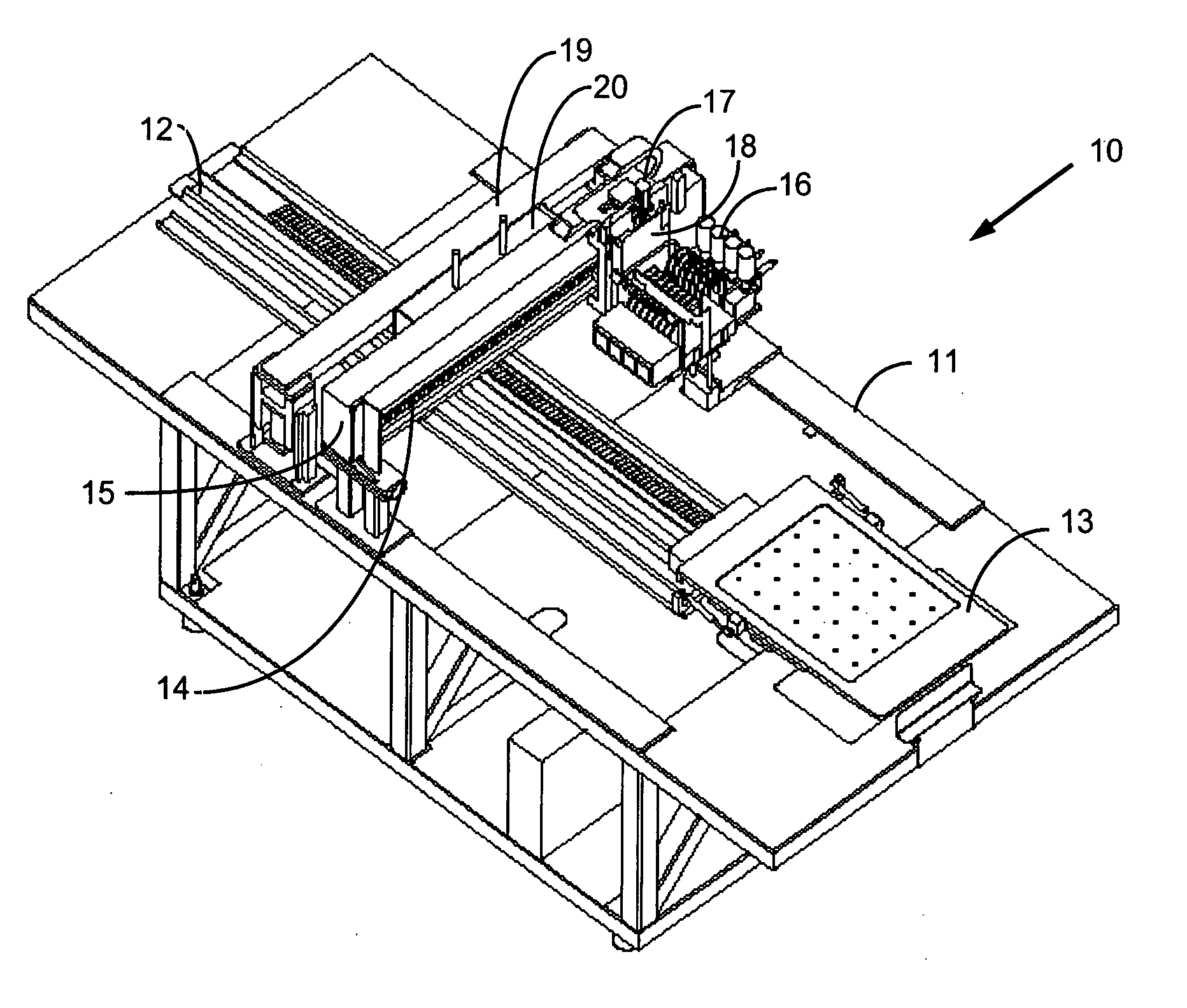
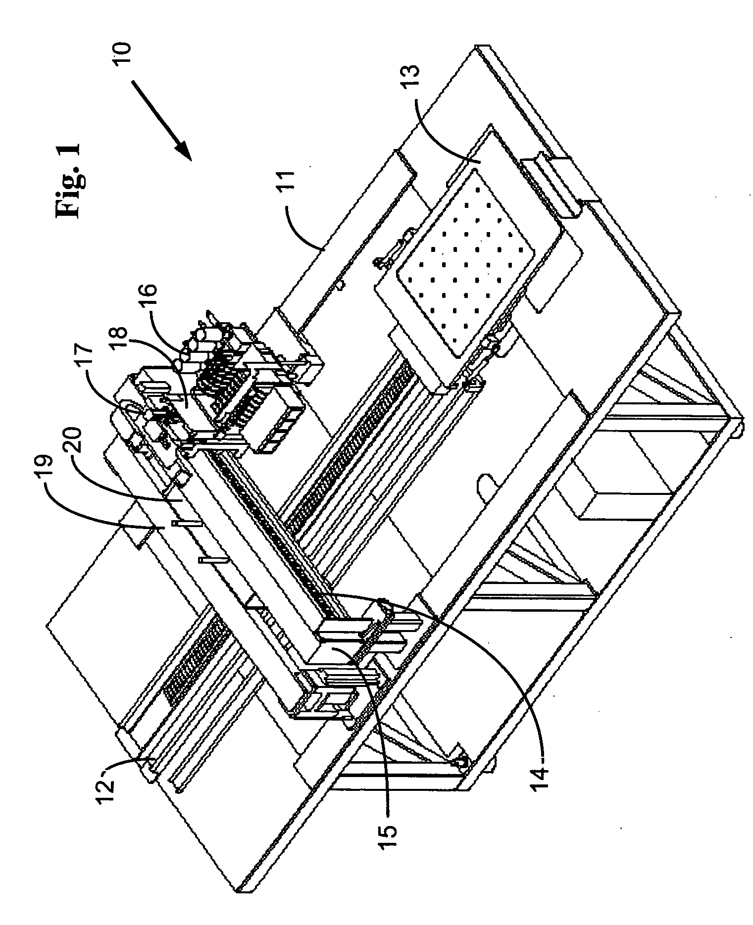
[0436] A 100% cotton shirt was mounted onto the machine, as described above, and a multicolor image was directly printed on the fabric surface using an inkjet printing heads.

[0437] The printed image was then subjected to curing, by heating to 150-180° C. for 180 seconds using an infrared curing unit.

[0438]FIGS. 16A and 16B present photographs of the front side (FIG. 16A) and the back side (FIG. 16B) of the printed shirt and demonstrate the dullness of the obtained image and the colors bleeding (especially that of the cyan) obtained on the front side, and the high absorption of the ink in the fabric, as shown by the significant infiltration of the ink through the fabric and to the back side of the shirt.

example 2

[0439] The same ink composition as in Example 1 was used for printing the same image, upon wetting the cotton shirt with an exemplary wetting composition according to the present invention.

[0440] Thus, a 100% cotton shirt was mounted onto the machine, as described above. 100% isopropanol was uniformly applied onto an area of the cotton fabric, using a spraying nozzle, at a density of 0.25 grams per cm2 area of the cotton fabric.

[0441] Immediately thereafter, while the cotton fabric was still wet with the isopropanol, the image was printed on the wet area of the shirt surface using an inkjet printing head and the ink composition described above.

[0442] The printed image was then subjected to curing, by heating to 150-180° C. for 180 seconds using an infrared curing unit.

[0443]FIGS. 17A and 17B presents photographs of the front side (FIG. 17A) and the back side (FIG. 17B) of the printed shirt, and clearly demonstrate the superior brightness of the obtained image and the absence of ...

example 3

[0444] A non-aqueous solvent-based ink composition having the four basic formulations of cyan, magenta, yellow and black colors (CMYK) was used.

[0445] A 100% cotton shirt was mounted onto the machine, as described above, and a multicolor image of squares of each color formulation was directly printed on the fabric surface using an inkjet printing heads.

[0446] The printed image was then subjected to curing, by heating to 150-180° C. for 180 seconds using an infrared curing unit.

[0447] In a parallel test, the same process was repeated while uniformly applying 100% isopropanol onto an area of the cotton fabric prior to applying the ink formulations, as described hereinabove in Example 2.

[0448] The optical density of each of the colored squares, in each of the printed shirts (with and without pre-treatment with a wetting composition according to the present invention) was measured, using Shamrock Color Print 415. Table 1 below presents the optical densities values that were recorded...


PUM

PropertyMeasurementUnit
Viscosityaaaaaaaaaa
Electric chargeaaaaaaaaaa
Adhesion strengthaaaaaaaaaa

Abstract

A novel process for printing high quality, high resolution, multi-color images on fibrous or porous materials or other ink absorbing materials, or on materials having high surface tension with a liquid ink, and especially over garments, is disclosed. The process is effected by applying a wetting composition, prior to, concomitant with and/or subsequent to applying an ink composition and formation of the images. Pre-printing and printing systems for executing the above process are further disclosed.

Description

RELATED APPLICATIONS [0001] This application is a Continuation-In-Part of PCT International Applications Nos. PCT / IL2005 / 000558 and PCT / IL2005 / 000559, both filed May 30, 2005, and both of which are Continuation-In-Part Applications of PCT International Application No. PCT / IL2005 / 000166, filed Feb. 10, 2005. [0002] PCT International Applications Nos. PCT / IL2005 / 000558 and PCT / IL2005 / 000559 also claim the benefit of U.S. Provisional Patent Application No. 60 / 651,230, filed Feb. 10, 2005, and Israel Patent Applications Nos. 163459, filed Aug. 11, 2004 and 162231, filed May 30, 2004. [0003] This Application also claims the benefit of U.S. Provisional Patent Application No. 60 / 759,955, filed Jan. 19, 2006. [0004] This Application is also a Continuation-In-Part of U.S. patent application Ser. No. 11 / 588,277, filed Oct. 27, 2006, which is a Continuation-In-Part of U.S. patent application Ser. No. 10 / 461,414, filed Jun. 16, 2003, now U.S. Pat. No. 7,134,749. The teachings of all the above A...

Claims


Application Information

Patent Timeline
IPC IPC(8): B41J2/01
CPCB41J3/28B41J3/407B41J3/4078B41J11/002C09D11/30D06P1/5257D06P1/625D06P1/65112D06P1/65118D06P1/65125D06P1/65131D06P5/2077D06P5/30B41M5/0011B41M5/0047B41M5/0058B41M5/0064B41M5/007B41M5/0076B41J11/00216
Inventor PEARL, YOSSIBEN-ZUR, OFER
Owner KORNIT DIGITAL LTD
Why Eureka
Try Eureka