Solid Oxide Fuel Cell Device and System, Method of Using and Method of Making

Inactive Publication Date: 2007-05-10
DEVOE ALAN +1
View PDF37 Cites 24 Cited by
  • Summary
  • Abstract
  • Description
  • Claims
  • Application Information

AI Technical Summary

Benefits of technology

[0011] According to one embodiment, the invention provides a solid oxide fuel cell device comprising an elongate substrate having a first end and an opposing second end with a length therebetween, a cold zone along a first portion of the length adjacent the first end, and a hot reaction zone along a second portion of the length adjacent the second end, wherein the hot reaction zone is configured to be heated to an operating reaction temperature, and the cold zone is configured to remain at a low temperature below the operating reaction temperature. A fuel inlet is positioned in the cold zone coupled to an elongate fuel passage extending through the hot reaction zone within the elongate substrate to a respective fuel outlet adjacent the first end. Similarly, an oxidizer inlet is positioned in the cold zone coupled to an elongate oxidizer pas

Problems solved by technology

There are several main technical problems that have stymied the successful implementation of SOFCs.
One problem is the need to prevent cracking of the ceramic elements during heating.
A second key challenge is to make contact to the SOFC.
Connecting at high temperature is problematic because organic material cannot be used, so one must use glass seals or mechanical seals.
These are unreliable, in part, because of expansion problems.
They can also be expensive.
Thus, previous SOFC systems have difficulty with at least the two problems cited above.
The plate technology also has difficulty with the edges of the plates in terms of sealing the gas ports, and has difficulty with fast heating, as well as cracking.
The tube approach resolves the cracking issue but still has oth

Method used


Image

  • Solid Oxide Fuel Cell Device and System, Method of Using and Method of Making
  • Solid Oxide Fuel Cell Device and System, Method of Using and Method of Making
  • Solid Oxide Fuel Cell Device and System, Method of Using and Method of Making

Examples


Embodiment Construction

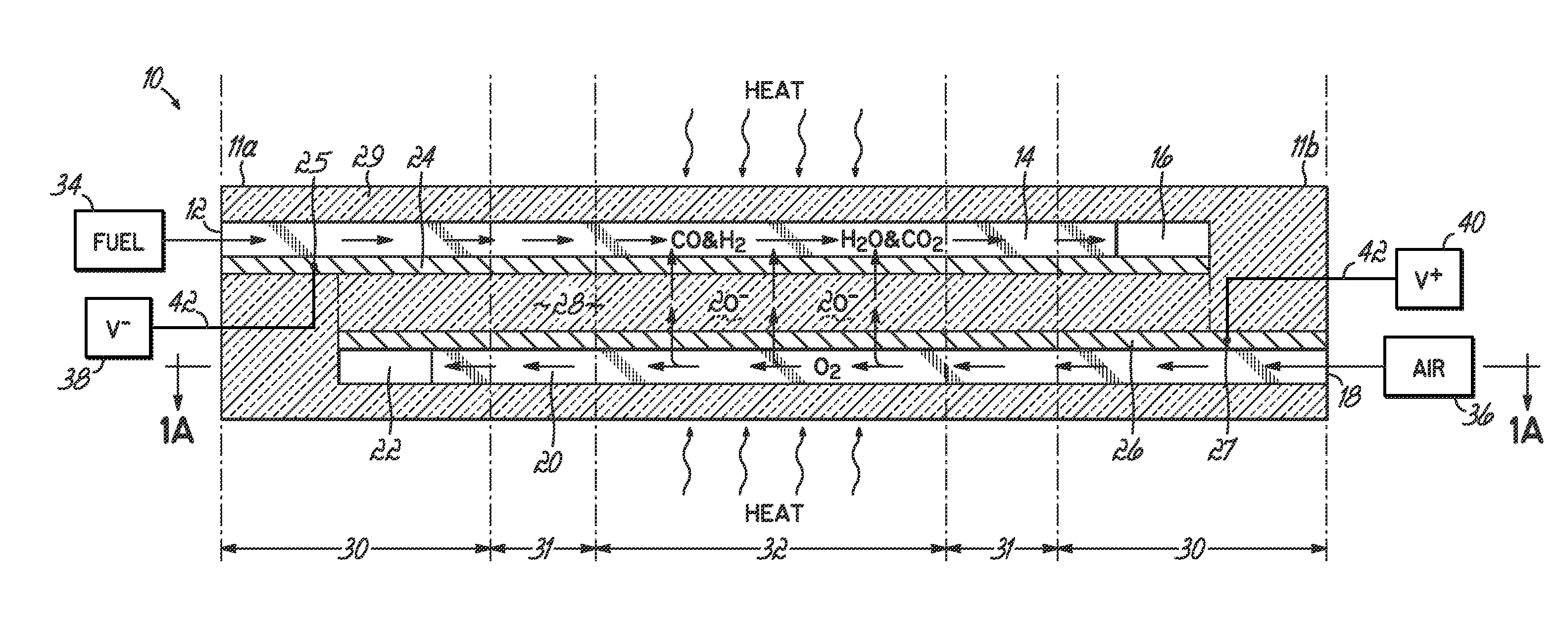
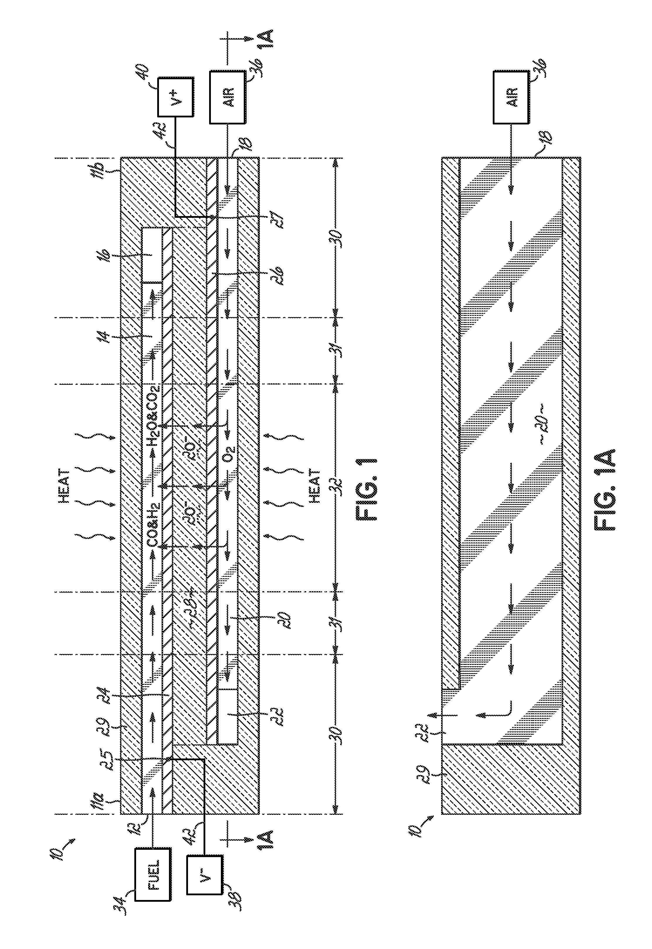
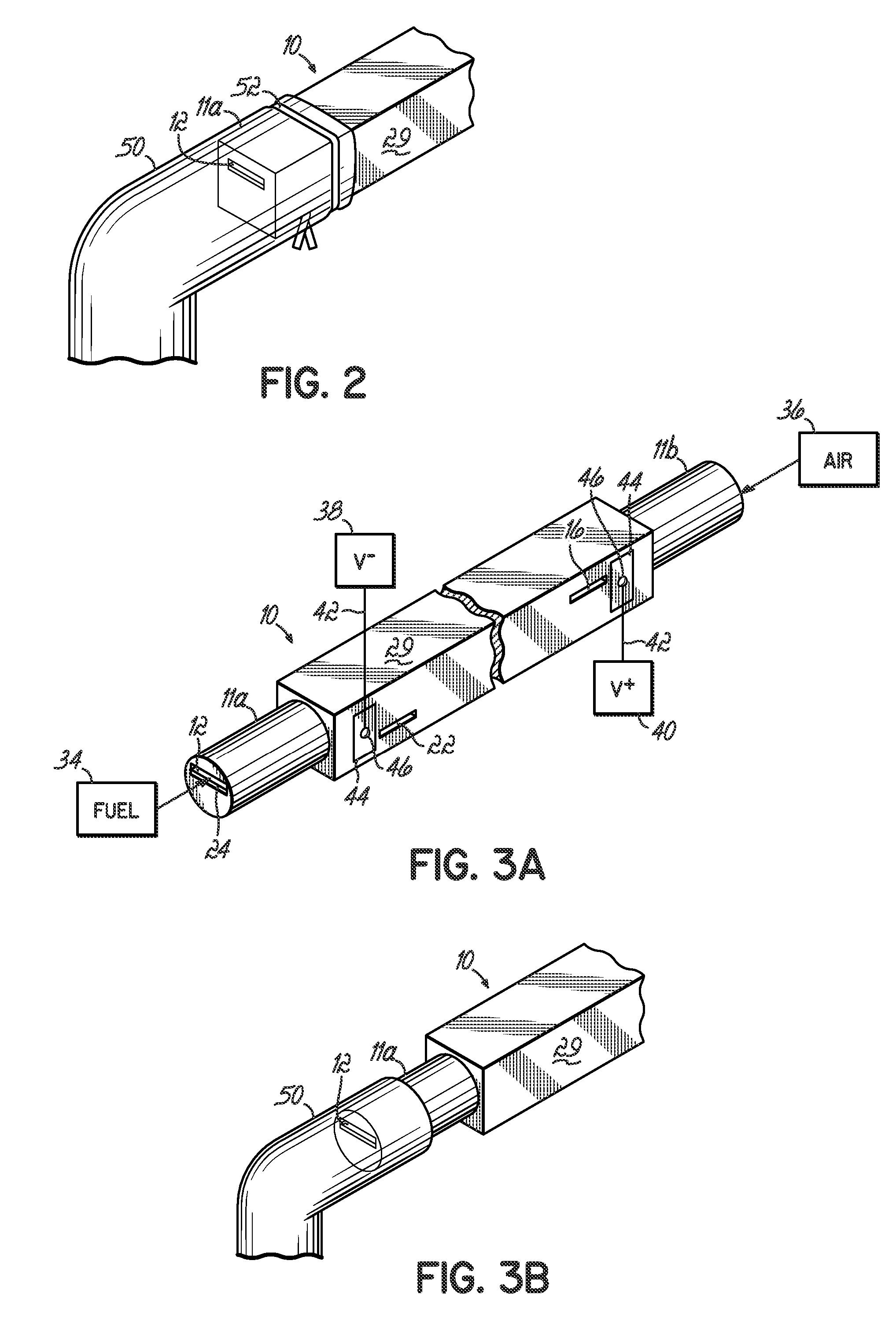
[0055] In one embodiment, the invention provides a SOFC device and system in which the fuel port and the air port are made in one monolithic structure. In one embodiment, the SOFC device is an elongate structure, essentially a relatively flat or rectangular stick (and thus, referred to as a SOFC Stick™ device), in which the length is considerably greater than the width or thickness. The SOFC Stick™ devices are capable of having cold ends while the center is hot (cold ends being 400° C., and most likely >700° C.). Slow heat conduction of ceramic can prevent the hot center from fully heating the colder ends. In addition, the ends are quickly radiating away any heat that arrives there. The invention includes the realization that by having cold ends for connection, it is possible to make easier connection to the anode, cathode, fuel inlet and H2O CO2 outlet, and air inlet and air outlet. While tubular fuel cell constructions are also capable of having cold ends with a hot center, the pr...


PUM


Abstract

A solid oxide fuel cell device that includes an elongate substrate having a first end and an opposing second end with a length therebetween, a cold zone along a first portion of the length adjacent the first end, and a hot reaction zone along a second portion of the length adjacent the second end. The hot reaction zone is configured to be heated to an operating reaction temperature, and the cold zone is configured to remain at a low temperature below the operating reaction temperature. A fuel inlet and air inlet are each positioned in the cold zone and coupled to respective elongate fuel and oxidizer passages that extend through the hot reaction zone within the elongate substrate in parallel and opposing relation to respective fuel and air outlets adjacent the first end. An anode and a cathode are each positioned adjacent a respective fuel and oxidizer passage in the hot reaction zone within the elongate substrate and each is electrically coupled to a respective first and second exterior contact surface on the elongate substrate in the cold zone. A solid electrolyte is positioned between the anode and cathode, and negative and positive electrical connections are made to the respective first and second exterior contact surfaces. A fuel cell system is also provided incorporating a plurality of the fuel devices with their hot reaction zones positioned in a hot zone chamber and their cold zones extending outside the hot zone chamber. A heat source is coupled to the hot zone chamber to heat the reaction zones to the operating reaction temperature. Fuel and air supplies are coupled outside the hot zone chamber to the cold zones for supplying fuel and air flows into the respective fuel and oxidizer passages. A method of making a solid oxide fuel cell device is also provided in which fluid anode and cathode materials are flowed into passages followed by liquid removal to thereby form anodes and cathodes in the passages.

Description

CROSS-REFERENCE TO RELATED APPLICATIONS [0001] Pursuant to 37 C.F.R. § 1.78(a)(4), this application claims the benefit of and priority to prior filed co-pending Provisional Application Ser. No. 60 / 734,554, filed Nov. 8, 2005, and prior filed co-pending Provisional Application Ser. No. 60 / 747,013, filed May 11, 2006, each of which is expressly incorporated herein by reference.FIELD OF THE INVENTION [0002] This invention relates to solid oxide fuel cell devices and systems, and methods of manufacturing the devices, and more particularly, to a solid oxide fuel cell device in the form of a multi-layer monolithic SOFC Stick™. BACKGROUND OF INVENTION [0003] Ceramic tubes have found a use in the manufacture of Solid Oxide Fuel Cells (SOFCs). There are several types of fuel cells, each offering a different mechanism of converting fuel and air to produce electricity without combustion. In SOFCs, the barrier layer (the “electrolyte”) between the fuel and the air is a ceramic layer, which allo...

Claims


Application Information

Patent Timeline
IPC IPC(8): H01M8/24H01M8/04H01M8/12B05D5/12H01M4/88
CPCH01M4/8817Y02E60/525H01M4/8842H01M8/006H01M8/0206H01M8/0215H01M8/0247H01M8/0252H01M8/0256H01M8/0258H01M8/0263H01M8/0265H01M8/0267H01M8/04007H01M8/04074H01M8/04089H01M8/04201H01M8/1213H01M8/1226H01M8/1246H01M8/1286H01M8/2425H01M8/243H01M8/2435H01M8/2485H01M2008/1293Y02E60/521H01M4/8828H01M8/2484Y02E60/50Y02P70/50H01M8/04H01M8/06H01M8/10H01M8/2432
Inventor DEVOE, ALANDEVOE, LAMBERT
Owner DEVOE ALAN
Why Eureka
Try Eureka