
Apparatus and method for performing radiation energy treatments

a radiation energy treatment and apparatus technology, applied in the field of apparatus and method for performing radiation energy treatment, can solve the problems of varying the angle between the discharge end of such wand-like devices and the surface exposed, the most difficult to accurately control, and the area exposed to laser energy

Inactive Publication Date: 2007-05-10
SIEGEL JERRY
View PDF24 Cites 25 Cited by
  • Summary
  • Abstract
  • Description
  • Claims
  • Application Information

AI Technical Summary

Benefits of technology

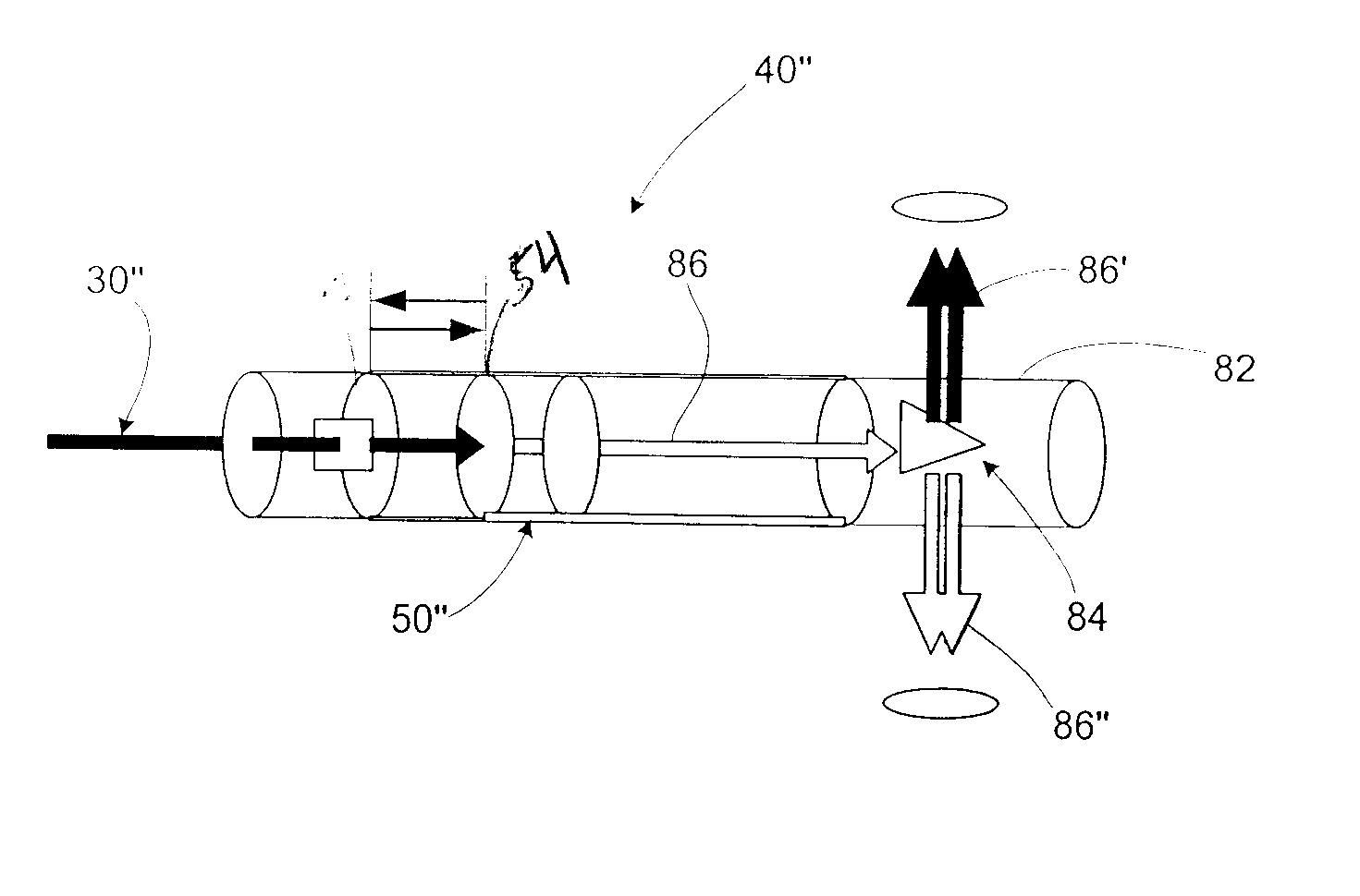
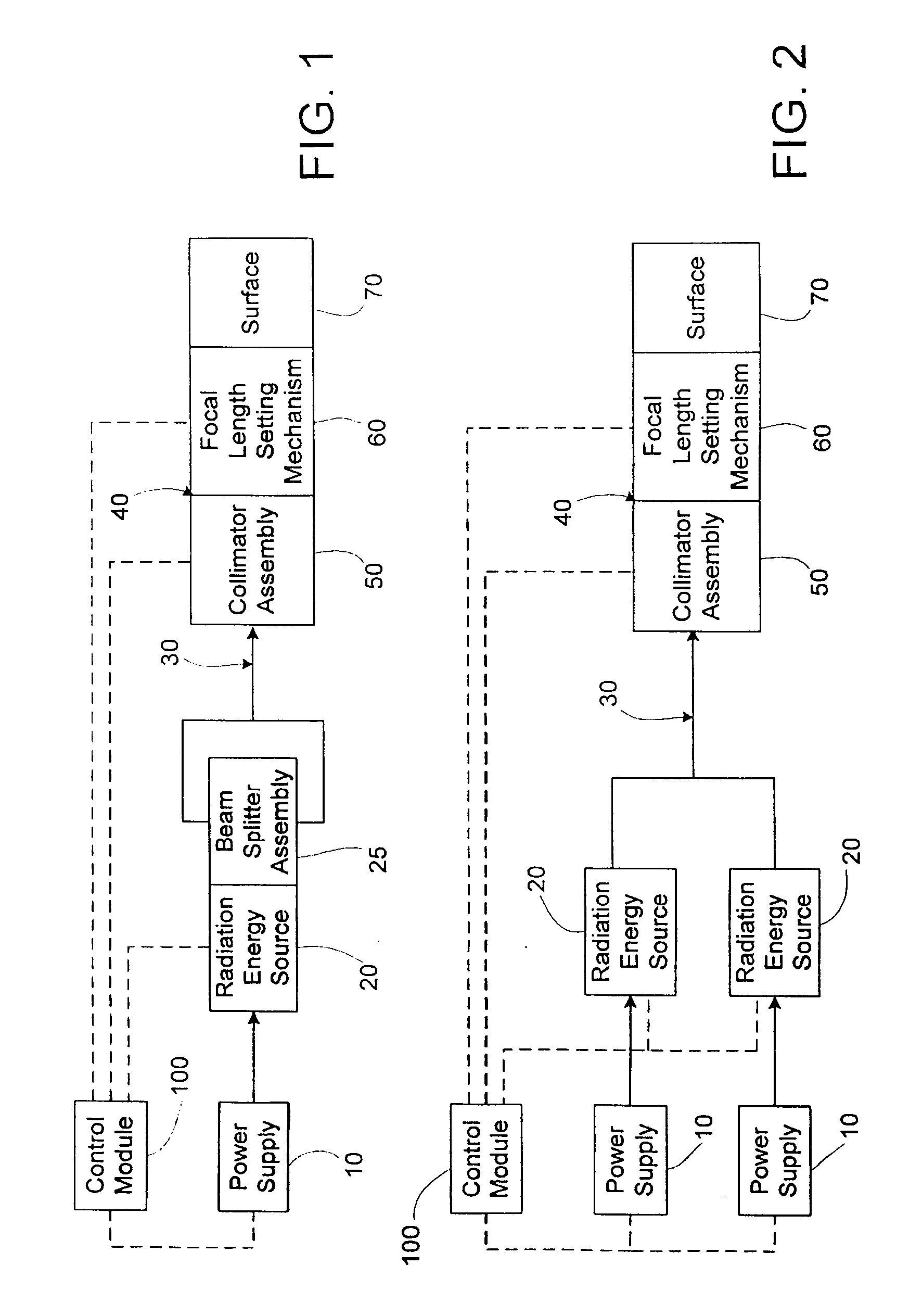
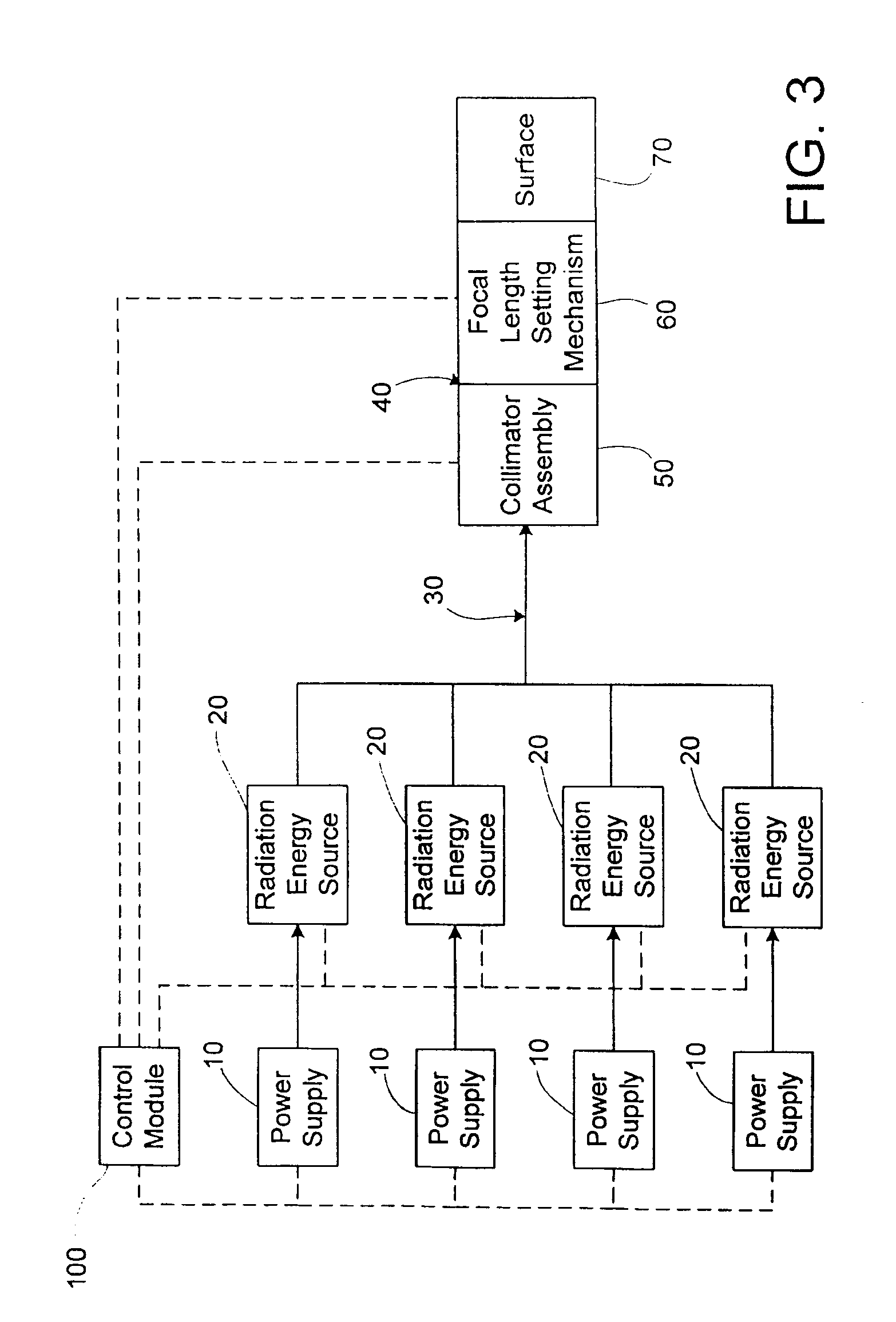
[0018] The present invention is directed to an apparatus and a method for performing non-invasive and invasive radiation energy treatments, including at least photo-stimulation, biostimulation, and / or photocollagen stimulation, on biological tissue. The apparatus includes at least one, but preferably a plurality of radiation energy sources structured to selectively emit radiation towards the biological tissue. The apparatus further includes an irradiation head assembly which includes an adjustable collector assemble structured to collect and redirect scattered and reflected radiation back to the treatment site, an adjustable collimator assembly structured to adjustably collimate the emitted radiation, and an adjustable focal length setting mechanism structured to securely set a desired focal length of the emitted radiation relative to the biological tissue.
[0022] Accordingly, a variety of specific energy densities can be achieved at a variety of wavelengths, at variety of absorption rates while maintaining the desired energy density and energy levels throughout a plurality of treatment ranges and over larger areas, thus allowing numerous treatment modalities to be performed with a single apparatus.
[0024] An illustrated embodiment of the present invention includes an irradiation head assembly which may comprise the adjustable collector assembly, the adjustable collimator assembly, and the adjustable focal length setting mechanism. The illustrated adjustable collector assembly includes a reflecting device or lens at the posterior of the assembly that facilitates in the reshaping and redirection of the reflected and scattered treatment radiation back onto the site of treatment. The entire collection assembly by shape form and function, increases the effectiveness of the radiation treatment by redirecting treatment radiation that would normally be lost and by increasing the safety for all who are in the treatment room by eliminating the risk of eye damage due to scattered or reflected radiation.
[0028] This is partly due to the fact that once a focal length is set, the distance between the outlet aperture and the contact surface is a fixed value. In a preferred embodiment of the present invention, the adjustable focal length setting mechanism is structured to set a plurality of focal lengths over a continuous range. The adjustable focal length setting mechanism thus provides a means to adjust and set the contact area or “spot size” of the combined emitted radiation, thus allowing the energy density to be precisely controlled during exposure of the biological tissue, which permits treatment over a larger “spot size” than would safely be possible otherwise. Indeed, the ultimate adjustment of the adjustable collimator and the adjustable focal length setting mechanism may utilize high power lasers and convert their ablative energy, thereby providing either biostimulation, photo-stimulation, or photocollagen stimulation by reducing the energy density via an increase in the divergence of the laser beam, and, therefore, the “spot size” at the affected area, thus providing a safe and desired energy density.

Problems solved by technology

In addition to the variability present in laser energy output and energy wavelength, perhaps the most critical variable in the medical application of laser beams, and among the most difficult to accurately control, is the energy density at the point of exposure of the biological tissue.
Even in the hands of the skilled medical laser operator, however, the distance and angle between the discharge end of such wand-like devices and the surface exposed are not precisely maintained, therefore, the area exposed to the laser energy often varies.
Further, even when a fixed laser beam is employed, control of the area exposed is difficult and imprecise.
First, the patient must be positioned the exact and correct distance from the laser beam to define the area of exposure, which is difficult to do with precision due to the distance between the laser beam and the patient.
In addition, the patient must be positioned such that the area exposed is at the correct angle relative to the fixed laser beam, again being difficult to do with precision due to the distance between them.
As may be appreciated, the control of the area exposed, and thus, the energy density to which biological tissue is exposed, by either of the above techniques is difficult at best.
Indeed, partly for this reason, known systems are configured to only treat very small areas, making the procedures very time consuming and as a result, more susceptible to error.
Furthermore, no one has described an apparatus that incorporates a device that comprises a collector with a reflecting lens that collects and then redirects the scattered and reflected radiation back to the site of treatment while utilizing either a single collimator or multiple collimators that are targetable and focusable and that include an adjustable focal length mechanism that emit coincident visible and infrared radiation, that can either intersect inside the targeted tissue or deploy in series upon the tissue, wherein the infrared radiation has a wavelength of approximately 1100 nm.

Method used


Image

  • Apparatus and method for performing radiation energy treatments
  • Apparatus and method for performing radiation energy treatments
  • Apparatus and method for performing radiation energy treatments

Examples


Embodiment Construction

[0054] As shown throughout the Figures, the present invention is directed to an apparatus and method for performing a plurality of radiation energy treatment, including at least photo-stimulation, biostimulation, photocollagen stimulation, and / or photobiostimulation, on biological tissue. The apparatus provides complete control of the energy density, area of treatment or “spot size”, and allows the utilization of specific wavelengths alone or in combination, either coincidentally or adjacently, as required for optimal penetration and absorption characteristics to selectively treat a specific tissue type and obtain the most beneficial results. As shown in FIG. 1, the laser treatment apparatus includes a power supply, which is shown schematically as 10, for at least one radiation energy source, shown schematically as 20, wherein the radiation energy output by the radiation energy source 20 is received by a transmission assembly, generally shown as 30, which transmits the radiation ene...


PUM


Abstract

An apparatus and method to apply photo-stimulation, photo-dynamic therapy and / or ablation laser treatment to biological tissue. The apparatus includes a plurality of radiation energy sources, preferably laser beams. Additionally, the apparatus allows either a single wavelength or a combination of various wavelengths, either coincidentally or adjacently, to be utilized to achieve a desired treatment effect. Laser beams are transmitted to the treatment area by one or more fiber optic cables which terminate at an assembly structured to collimate the emitted radiation prior to application to the tissue. In addition, the apparatus includes a focal length setting mechanism which assures that a constant, fixed distance exists between the point of discharge of the laser beam and the biological tissue, thus assuring a constant energy density at the point of application. A method is presented for applying photo-stimulation, photocollagen stimulation and / or ablation laser treatment utilizing the above apparatus.

Description

RELATED APPLICATIONS [0001] This application is a continuation-in-part of U.S. application Ser. No. 10 / 227,106 filed on Aug. 23, 2002, which claims the benefit under 35 USC 119(e) of earlier filed U.S. Provisional Application Ser. No. 60 / 314,938, filed on Aug. 23, 2001, both of which are hereby incorporated herein by reference in their entireties.FIELD OF THE INVENTION [0002] The present invention is directed to an apparatus and a method for performing radiation energy treatment on a target area of biological tissue, wherein the apparatus for performing radiation energy treatments on biological tissue is structured to provide a plurality of laser energy treatments comprising of at least but not limited to ablation, biostimulation, photo-stimulation, photocollagen regeneration, and photo-dynamic therapy, either separately or in conjunction with one another, utilizing low, medium, and / or high power lasers employing either a single wavelength or combining various wavelengths, either co...

Claims


Application Information

Patent Timeline
IPC IPC(8): A61B18/18A61N5/06
CPCA61B18/203A61B2018/00452A61B2018/207A61N5/0616A61N5/062A61N2005/063A61N2005/0644
Inventor SIEGEL, JERRY
Owner SIEGEL JERRY
Learn More