[0011] One of the advantages of having a movable pace / sense electrode used in conjunction with a passive restraint device such as the disclosed cardiac harness, is that it allows not only pacing and
defibrillation therapies, but also treats congestive
heart failure two different ways at the same time. Congestive heart failure is treated by the cardiac harness by
wall stress reduction and congestive heart failure also can be treated by biventricular pacing to increase heart pump efficiency. In fact, it is contemplated that these effects are not only additive, but may be synergistic in that the end results could be better than the individual contributions of the therapies separately. A further
advantage of providing movable pace / sense leads independently of the cardiac harness allows for optimization of the pace / sense function, and in the case of the cardiac harness having defibrillation electrodes attached to it, one can decouple the pace / sense function from the defibrillation function, thus allowing one to optimally place both devices for optimal defibrillation therapy and pace / sense therapy. Integrated intravenous lead systems do not allow decoupling of the pace / sense function from the defibrillation function since they are integrated and the positions of the electrodes are fixed relative to each other. Thus, an important
advantage of the present invention provides for the decoupling of the pace / sense function from the defibrillation function since the pace / sense electrodes can be moved independently to an optimal position on the heart during delivery.
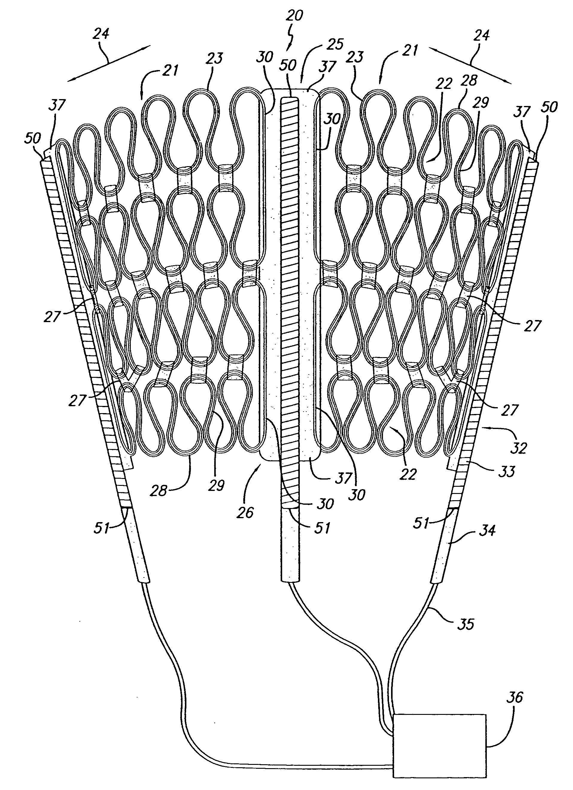
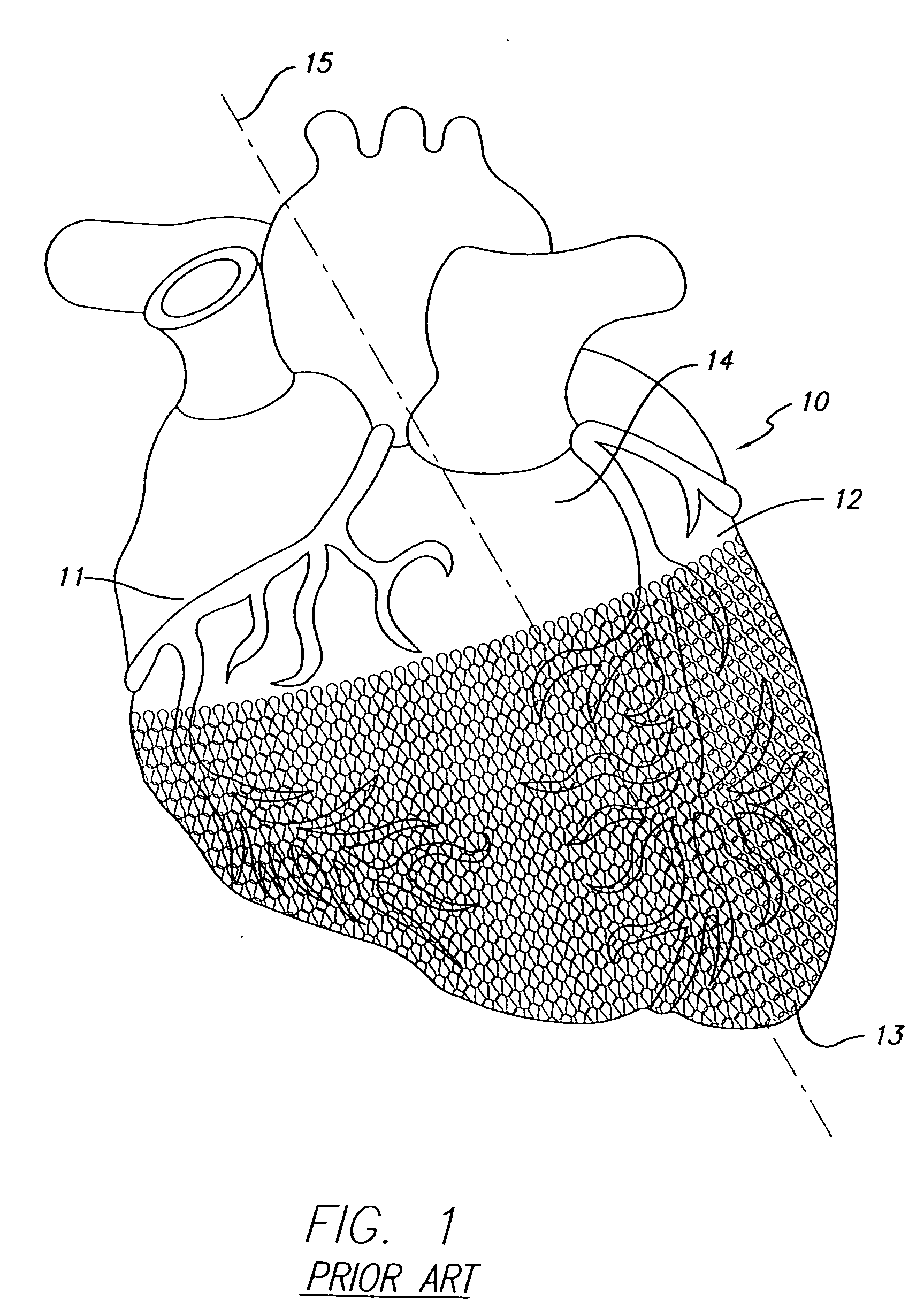
[0012] In one embodiment, a single pace / sense electrode (with optional defibrillation electrode) is attached to a delivery member that allows it to be slipped under a previously delivered cardiac harness. In this embodiment, the tension of the harness provides the compression required for the pace / sense electrodes to firmly contact the heart tissue. It may be necessary to provide a surface area on the pace / sense electrode at least as wide as a
cell on the cardiac harness to ensure a more even distribution of the compression. Preferably, a delivery member would be a flattened “
paddle-like” member that offers a low profile and resists side-to-side movement during advancement. The delivery member may be similar to the current push arm used to deploy the cardiac harness, though it may benefit from being wider, and having less of a “nub” at the end, and being either stiffer or more flexible. Holes in the delivery member offer the ability to secure the pace / sense electrode to the member with a thread-like material (release lines) and release it once it is in the desired position under the cardiac harness. As with other embodiments to be described, it is beneficial to connect the proximal end of the pace / sense electrode to a pace / sense analyzer prior to releasing the pace / sense electrode from the delivery member. This allows the user to make positional adjustments as necessary to optimize the desired
electrical performance and / or effect on resynchronization.
[0013] While the pace / sense electrode and delivery member could be manufactured and packaged together, it may be desirable to allow the user the ability to load a separate sterile pace / sense electrode into a sterile delivery member (in the
sterile field) at the time of
surgery. In one embodiment, the pace / sense electrode could be inserted under a loose release line mechanism on the delivery member that is then cinched down on the pace / sense electrode by the user prior to delivery.
[0014] In the embodiments just described, the pace / sense electrode is placed under the harness after the harness has been delivered. There is a benefit to having the separate pace / sense electrode be deployed onto the heart at the same time as the cardiac harness. The pace / sense electrodes could be laced to any of the same push arms as the cardiac harness, and released onto the heart at the same time as the cardiac harness. In another embodiment, the pace / sense electrodes could be laced directly to the cardiac harness (with or without the support of an independent set of push arms). In this case, the release lines attached to the pace / sense electrode and / or delivery member could be removed independently of the release lines that attach the push arms to the harness. This allows the user to adjust the harness and electrodes together after the harness is deployed and the primary harness
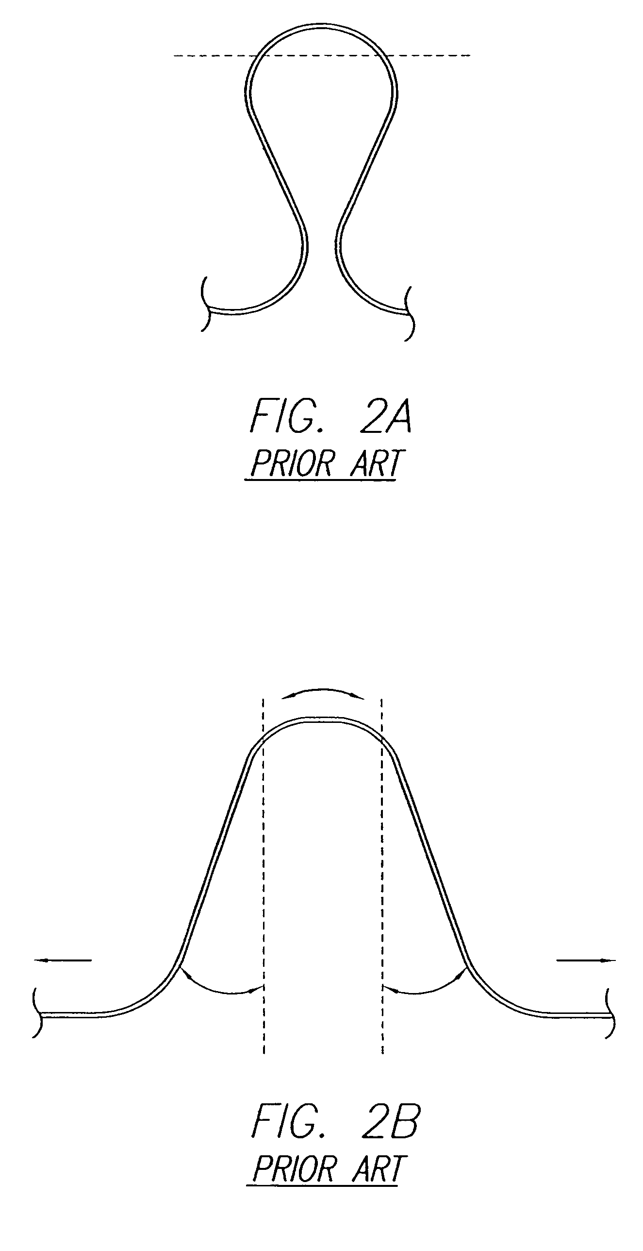
delivery system removed. In another embodiment, the pace / sense electrodes could be laced to delivery members that are positioned under the cardiac harness, but are not attached to the harness. There is an added benefit of this configuration in that the delivery members provide support to the harness to help prevent row flipping and
cell interlocks as the harness is advanced onto the heart. In another embodiment, the delivery members are attached to the same slider as the push arms laced to the cardiac harness and all release lines are connected to the same pull ring. In another embodiment, the delivery members are attached to a separate sliding mechanism, preferably in front of the slider to which the push arms are connected. Alternatively, there could be one sliding mechanism, but the delivery members could be detached from it after deployment onto the heart. At this point, usage of the delivery members would be similar to the case of having a separate sliding mechanism. Either way, the release lines from the pace / sense electrodes and the cardiac harness are connected to separate removal mechanisms. The pace / sense electrodes may be able to be released independently of the other electrodes. The delivery members may also be removed from the slider independently of one another. This allows the pace / sense electrodes to be advanced either ahead of or with the cardiac harness. It also allows the removal of the primary cardiac harness
delivery system, leaving behind the delivery members attached to the pace / sense electrodes. Each pace / sense electrode may then be manipulated under the harness as necessary before being released from the delivery member in order to find the optimal position on the heart for the pace / sense therapy.
[0015] It should be noted that the same or similar pace / sense electrode delivery techniques described above could be used to deploy a pace / sense electrode onto any position on the surface of the heart, including the right or
left atrium. There are particular advantages of being able to place a pace / sense electrode on the
left atrial epicardial surface. As is typically recommended for CRT procedures, atrial sensing and optional pacing allows for improved timing between atrial and ventricular contractions (assuming a ventricular pace / sense electrode is present). Placement of a pace / sense electrode onto the atrial epicardial surface prevents the need for
venous access to the
right atrium, thus allowing the cardiothoracic surgeon to perform the whole procedure. It also allows the possibility of
left atrial electrode placement, which is not feasible from a venous approach.
Left atrial sensing and optional pacing particularly optimizes
left atrial and left
ventricular contraction timing.
[0016] In the described embodiments, consideration is made for the interaction of the cardiac harness and the pace / sense electrode, which relies on the tension of the harness to hold the electrode in place. It may be that once the harness and pace / sense electrode are fibrosed in place, little
relative motion exists. However, this may not be the case thereby requiring features in the pace / sense electrode and / or the cardiac harness to minimize relative movement between the devices, or if
relative motion exists, minimize the friction or propensity for material abrasion in the chronic setting. Because
silicone rubber in its unaltered cured state can abrade against itself and against other materials, it may be important to utilize implantable materials in the cardiac harness, and / or the pace / sense electrodes that are positioned against it, that have more abrasion resistant surfaces. Examples of abrasion resistant materials include, but are not limited to, application of a lubricious
silicone oil or
hydrophilic coating to the lead
body surface;
silicone extruded tubing (e.g.,
platinum-cured Nusil 4755) which has the
surface modified with
plasma; oxidative reduction of the silicone surface to a
silicon suboxide;
plasma enhanced
chemical vapor deposition of a
silicon suboxide (these processes should reduce the tackiness of the surface and increase
toughness); silicone extruded tubing that has a Teflon or
Parylene deposited upon the surface; a sleeve of TEFLON or ePTFE over the surface of the pace / sense electrode (the material could also be used in place of silicone); matrix of braided or wound fibers (e.g., TEFLON,
polypropylene, or
polyester) or a matrix of an otherwise porous material (e.g., ePTFE), impregnated with silicone or another implantable elastic material; silicone extruded tubing with a layer of
polyurethane (e.g., 55D
polyurethane, a more lubricious and abrasion
resist implantable material) over the surface (either as a sleeve slipped over the surface, a sleeve melted down onto the surface, or coextruded onto the surface);
polyurethane used in place of silicone; and a chemical blend of silicone and polyurethane, such as Elast-Eon 2A, produced by Aortech Biomaterials plc. A pace / sense electrode covered by an ePTFE sheet may not only reduce
contact force (and frictional force), but the wireform harness may sink down to be flush with the top surface of the ePTFE, and the
contact force (and frictional force) could be reduced to zero, thus eliminating the frictional and wear abrasion concerns between two devices in contact on a
beating heart.

