Photogravure press and method for manufacturing multilayer ceramic electronic component

Active Publication Date: 2007-05-17
MURATA MFG CO LTD
View PDF9 Cites 12 Cited by
  • Summary
  • Abstract
  • Description
  • Claims
  • Application Information

AI Technical Summary

Benefits of technology

[0032] When a gap of each cut is greater than the widths of the printing-direction walls and the perpendicular walls in the center portion of the print area, the printing paste flows better between the adjacent cells. Therefore, this also enables uniform thickness of the paste film formed by gravure printing.
[0033] When round or oblique chamfers are provided at leading ends of the perpendicular walls pointing toward the cuts, the printing paste flows better between the adjacent cells and the flow of stringiness is produced more smoothly, in a manner similar to that in the above-described case when the round or oblique chamfer is provided at the corner where a portion of the printing-direction wall and a portion of the perpendicular wall intersect. As a result, this further improves the smoothness of the paste film formed by gravure printing.
[0034] In the photogravure press according to preferred embodiments of the present invention, when the printing-direction walls substantially continuously extend from a print start side to a print end side of the print area, the printing paste flows in the printing direction only within a region surrounded by the printing-direction walls. Therefore, this is highly effective in avoiding surface irregularities of the paste film. Consequently, the thickness of the paste film formed by gravure printing is more reliably uniform.
[0035] When the cuts adjacent in the printing direction are shifted from each other in the direction that is substantially perpendicular to the printing direction,

Problems solved by technology

Therefore, this technique is unsuitable particularly for printing for forming a paste film having a relatively large area, and causes uneven printing.
Therefore, when printing paste having a relatively high viscosity, such as conductive paste, is used, flow of the printing paste between the adjacent cells is limited.
As a result, traces of the cells remain in a printed paste film, and a smooth paste film

Method used


Image

  • Photogravure press and method for manufacturing multilayer ceramic electronic component
  • Photogravure press and method for manufacturing multilayer ceramic electronic component
  • Photogravure press and method for manufacturing multilayer ceramic electronic component

Examples


Example

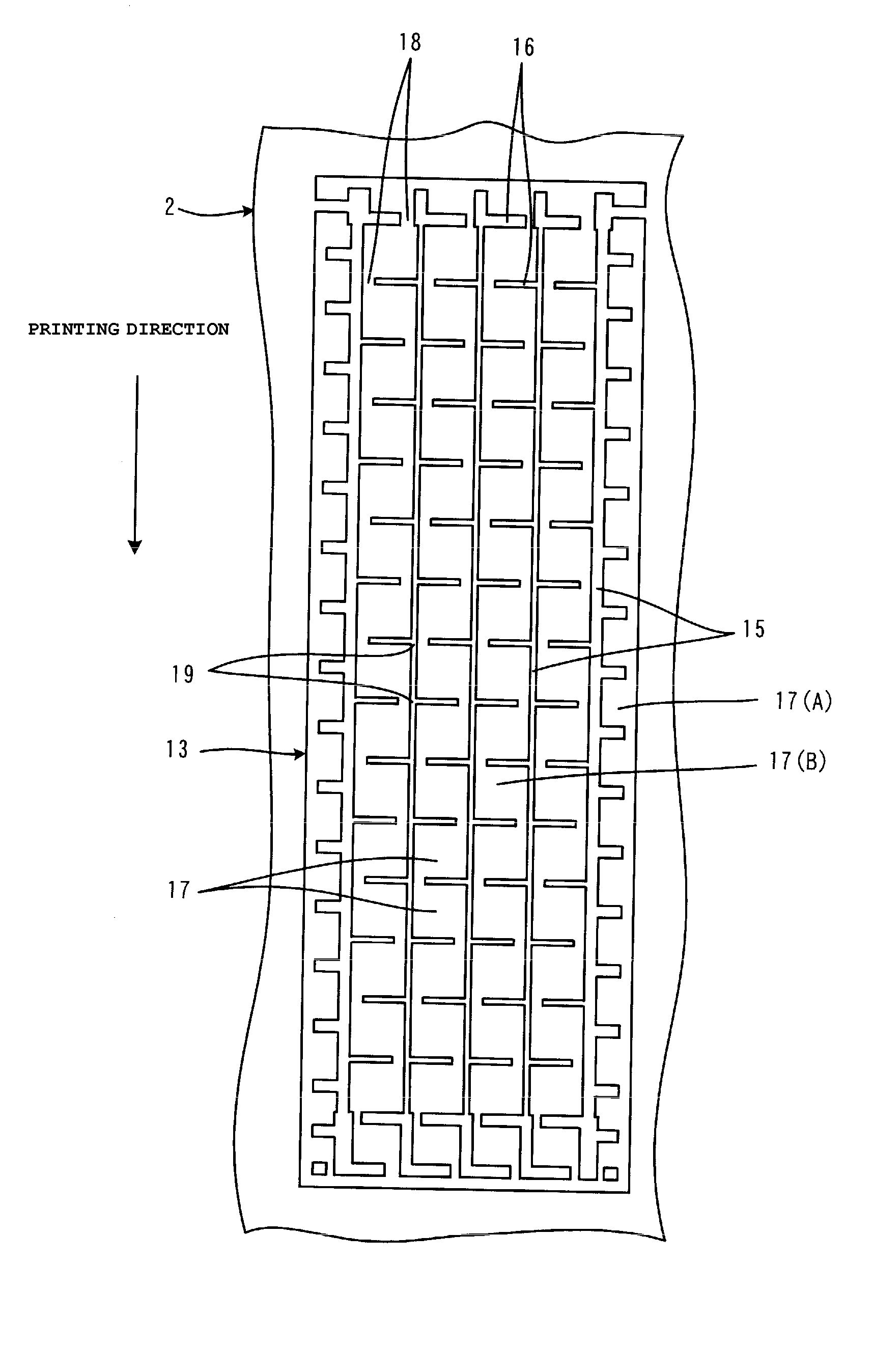
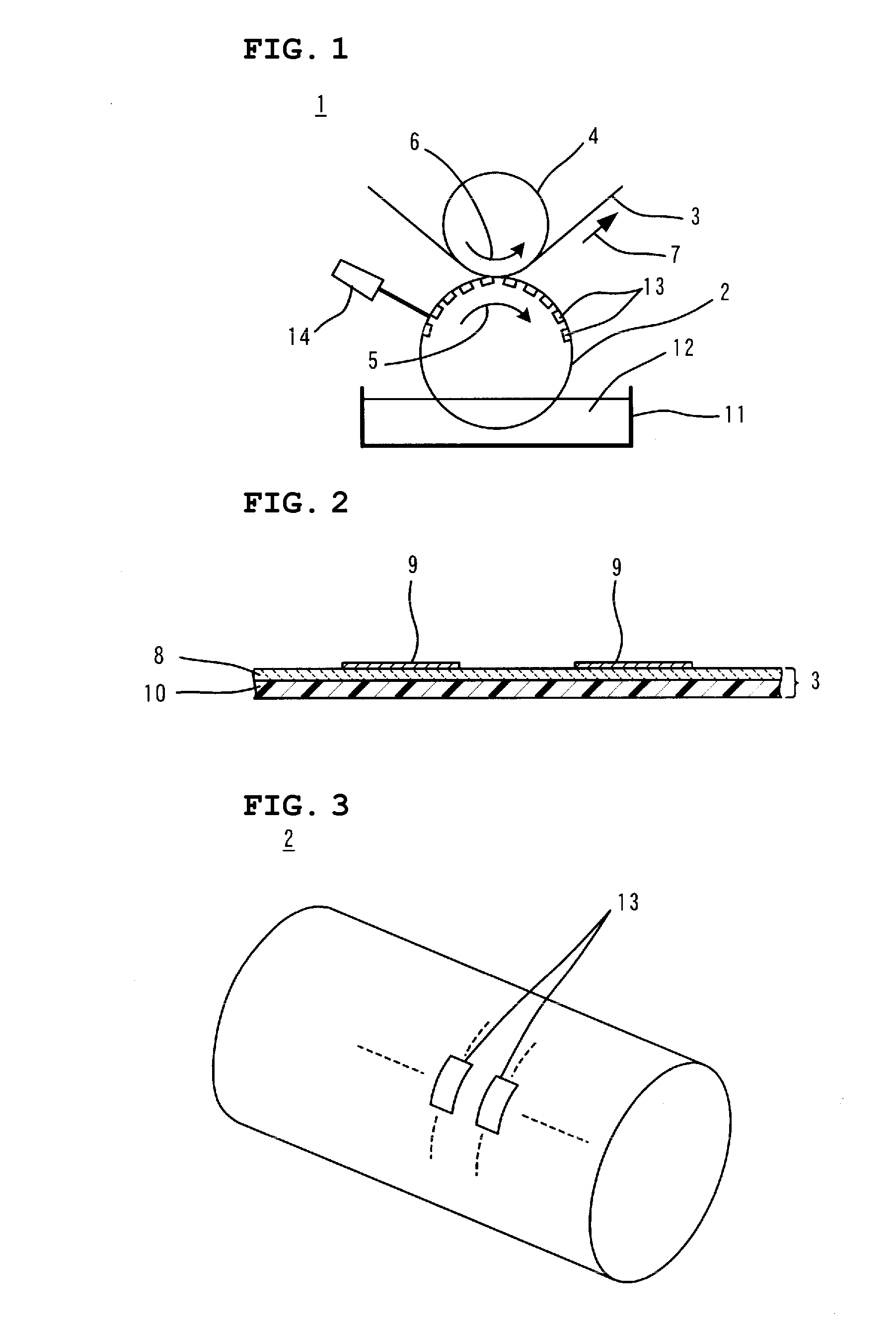
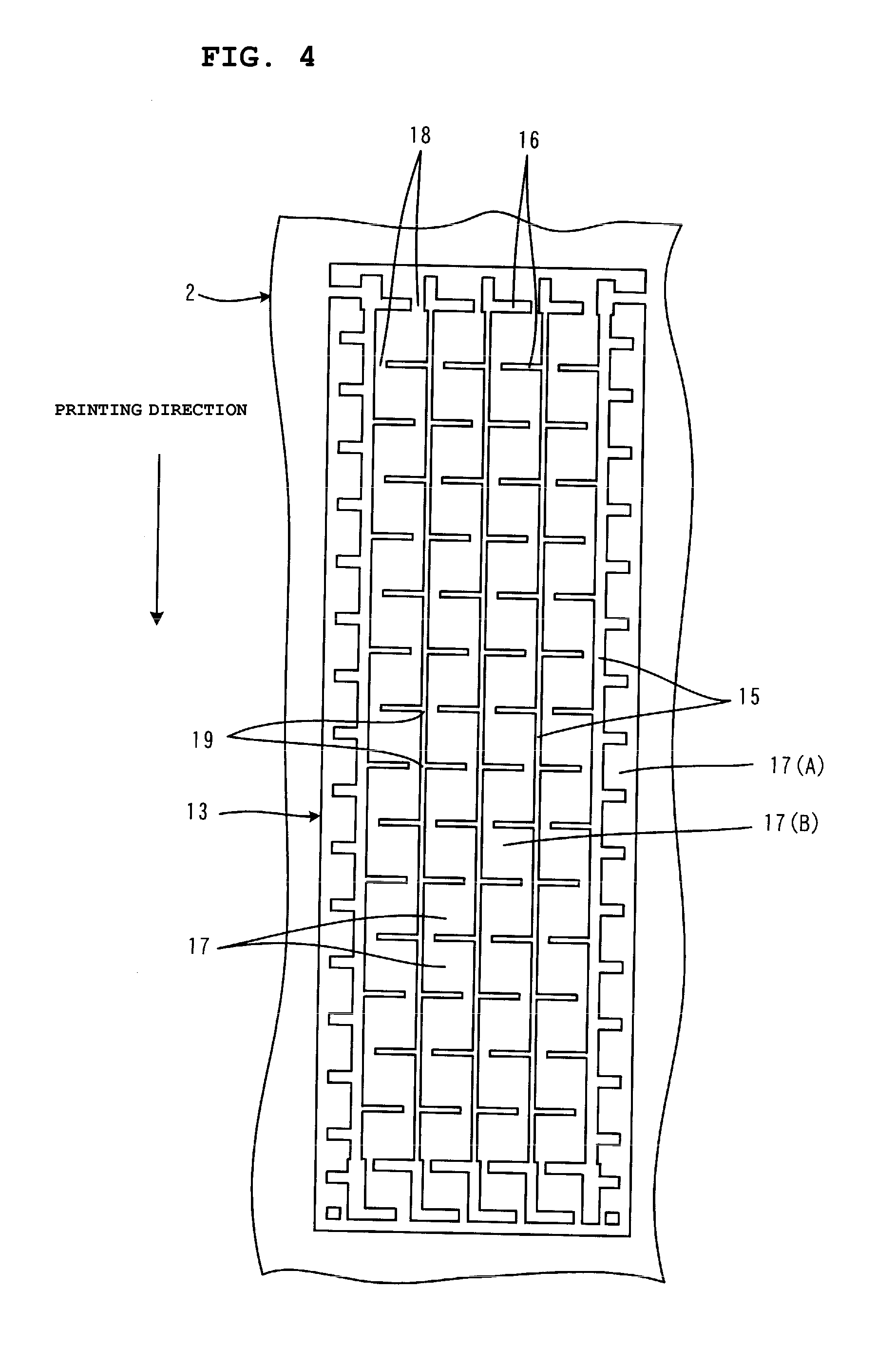
[0050]FIG. 1 is a front view schematically showing a photogravure press 1 according to a first preferred embodiment of the present invention.

[0051] The photogravure press 1 preferably includes a gravure roll 2, and an impression cylinder 4 facing the gravure roll 2 with a printing sheet 3 disposed therebetween. The gravure roll 2 and the impression cylinder 4 rotate in the directions of arrows 5 and 6, respectively, whereby the printing sheet 3 is conveyed in the direction of arrow 7. Incidentally, there are photogravure presses that do not include an impression cylinder, for example, a photogravure offset press.

[0052] The photogravure press 1 is used to manufacture a multilayer ceramic electronic component, such as a multilayer ceramic capacitor, for example. More particularly, the photogravure press 1 is used to form paste films, which are to be patterned layers defining a portion of a multilayer structure provided in the multilayer ceramic electronic component, on the printing ...


PUM

PropertyMeasurementUnit
Electrical conductoraaaaaaaaaa
Areaaaaaaaaaaa

Abstract

In a print area provided on a peripheral surface of a gravure roll, a plurality of cells are defined by printing-direction walls and perpendicular walls, and each perpendicular wall has a plurality of cuts. In a center portion of the print area, most intersections of the printing-direction walls and the perpendicular walls are defined by T-shaped intersections where the perpendicular walls do not cross the printing-direction walls, but meet the printing-direction walls in a T-shaped arrangement. Preferably, round chamfers are provided at corners where a portion of each printing-direction wall and a portion of each perpendicular wall intersect, and at leading ends of the perpendicular walls pointing toward the cuts.

Description

BACKGROUND OF THE INVENTION [0001] 1. Field of the Invention [0002] The present invention relates to a photogravure press and a method for manufacturing a multilayer ceramic electronic component performed with the photogravure press, and more particularly, to a technique for enhancing the smoothness of a paste film formed by gravure printing. [0003] 2. Description of the Related Art [0004] In order to manufacture a multilayer ceramic electronic component, such as a multilayer ceramic capacitor, for example, a step of forming a conductive paste film defining an internal electrode on a ceramic green sheet is performed. The internal electrode must have high patterning accuracy. As a technique that satisfies this requirement, gravure printing has been used (for example, see Patent Document 1). [0005] Japanese Unexamined Patent Application Publication No. 9-76459 (Patent Document 1) discloses that, of a plurality of cells provided in each print area provided on a peripheral surface of a ...

Claims


Application Information

Patent Timeline
IPC IPC(8): B41F9/00H01G13/00
CPCB41F9/00B41F9/063B41F13/11B41P2217/50H01G4/005H01G4/01H05K2203/0143H01G4/12H01G4/30H01G13/00H05K1/092H05K3/1275H05K2203/0113H01G4/012B41N1/06B41C1/02H05K3/12B41F17/14
Inventor TAKASHIMA, HIROYOSHIHASHIMOTO, AKIRATABATA, KAZUHIROKANAYAMA, YOSHIHIROTANABE, TAKASHIGE
Owner MURATA MFG CO LTD
Why Eureka
Try Eureka